Vermes
Advanced Member level 4
Presented here device can be used for a computer in 4.0 system for playing and listening to music (4 speakers). It uses two PCBs for TDA 2030, 120VA transformer from halogens (2x12V with modified windings), housing, heat sink, 8cm computer fan, meters and LM1036. Most of those components can be found in average electronics lab.
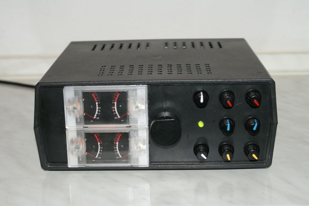
Large central knob adjusts the volume stage of all channels. Two small knobs with white strip adjust gain (0 to 100%) of front and rear speakers – front-back volume ratio setting. There is separate control of treble (knobs with red strip), bass (yellow strip) and balance (blue strip) for front and back. Meters indicate the power of each channel (0dB indicates the power of 10W/8ohm).
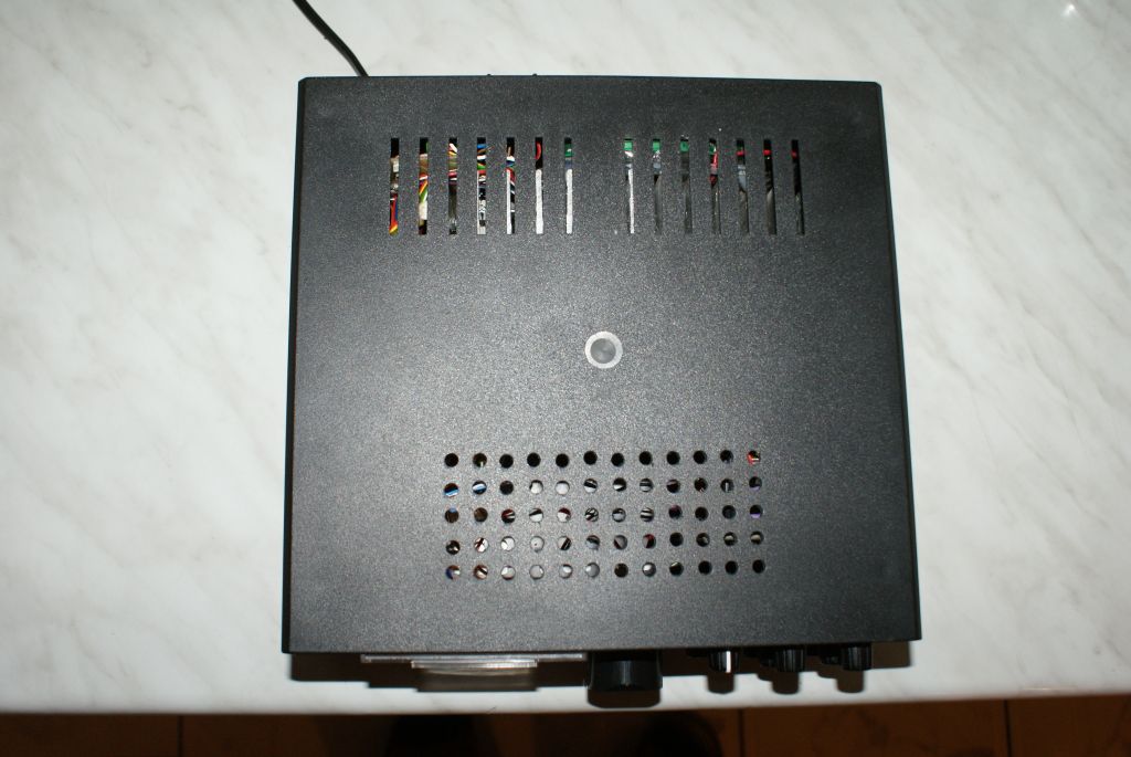
There is a supply cable, mains switch and speaker cables clamps on the back of the housing. Additional holes were drilled in the housing to provide right cooling. The whole is connected to the sound card Audigy 2 and powers 2 pairs of speakers.
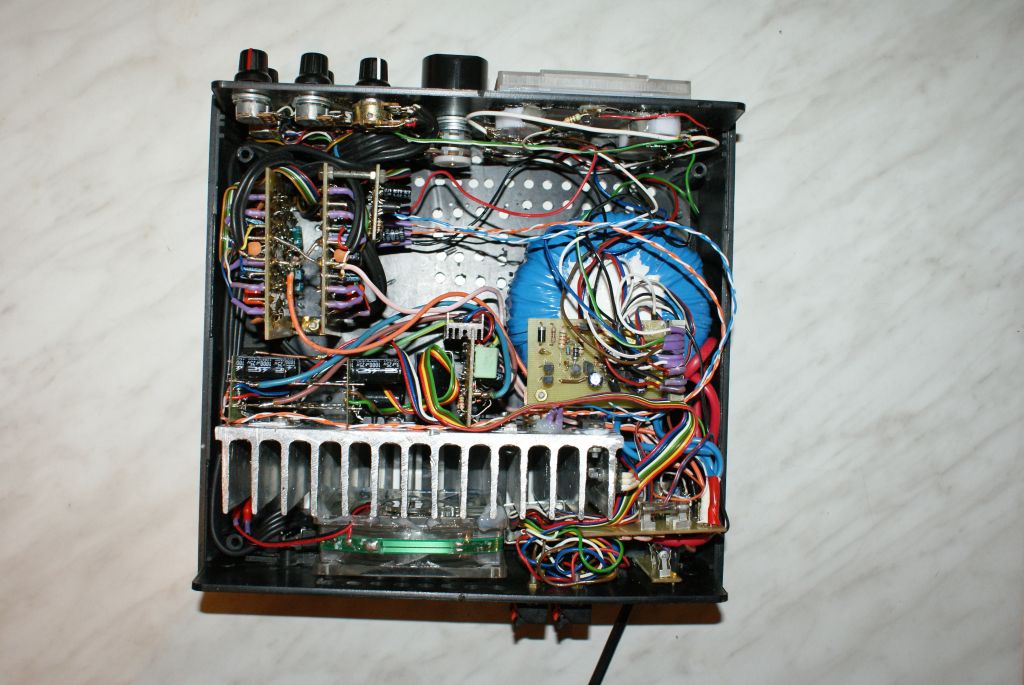
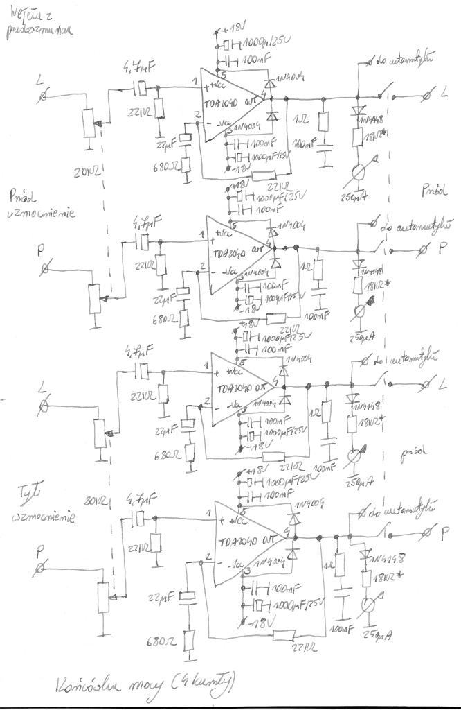
Power amplifier was made on four systems TDA 2040 mounted on PCBs of DIY sets for TDA 2030 screwed to the heat sink by bases with thermoconductive paste. Systems operate in a typical configuration with applied greater electrolytic capacitors (1000uF) and one capacitor for each voltage powering the power amplifiers 4700uF. Outputs of the power amplifiers are connected to the output clamps through a relay with 4 switchable contacts. There are additional 4 meters showing the output power.
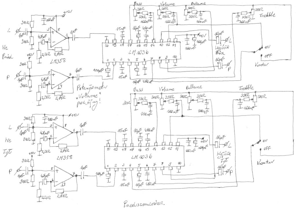
There is an amplifier on systems LM358 with 2,2x gain in the preamplifier. Initially stengthened signal is fed to systems LM1036, which act as the gain, balance, treble and bass regulators. The whole was mounted on specially designed for that purpose PCBs of one-sided laminate. Preamplifier with input sockets, power amplifiers, double potentiometers controlling the front and back gain are connected by shielded cables. Heat sink is connected to the ground of the system.
The power supply provides 3 voltages:
- +12V stabilized for the preamplifier supply implemented on uA723
- +18V and -18V stabilized for the power amplifier supply implemented on serial stabilizer
Rectifier bridge 10A, power transistors of the power supply were mounted on a heat sink on bases, common for the whole device. The whole is additionally protected by safety fuses and in the case of stabilizer +12V, electronic output current limitation.
Safety system consists of two parts:
- system for disconnecting the speakers when constant voltage appears at the output, switching the speakers with 2 seconds delay after turning the power on, and disconnecting immediately when the supply voltage is off, in order to eliminate the influence of unknown states of the amplifier to speaker sets.
- fan operation control system. Control turns on the fan when the hear sink reaches the temperature of 60 degrees Celsius and it turns the fan off when the heat sink is cooled to the temperature approximately 10 degrees Celsius lower.
Both systems are powered from a stabilizer 7912 which uses negative voltage of the supply of power amplifiers. Each blocks are on separate PCBs.
The amplifier can operate with 4ohm load, but it is connected with the modification (more powerful transformer, rectifier bridge, fuses).
In addition, you can also apply:
- third channel of the preamplifier on ML358 and LM1036 to support the central channel and bass channel
- power amplifier on TDA 2040 for the central channel
- active subwoofer output
- additional power amplifier on TDA 2040 with passive subwoofer output


Link to original thread - Wzmacniacz 4 kanałowy (4x15W) do komputera
Last edited:

