Vermes
Advanced Member level 4
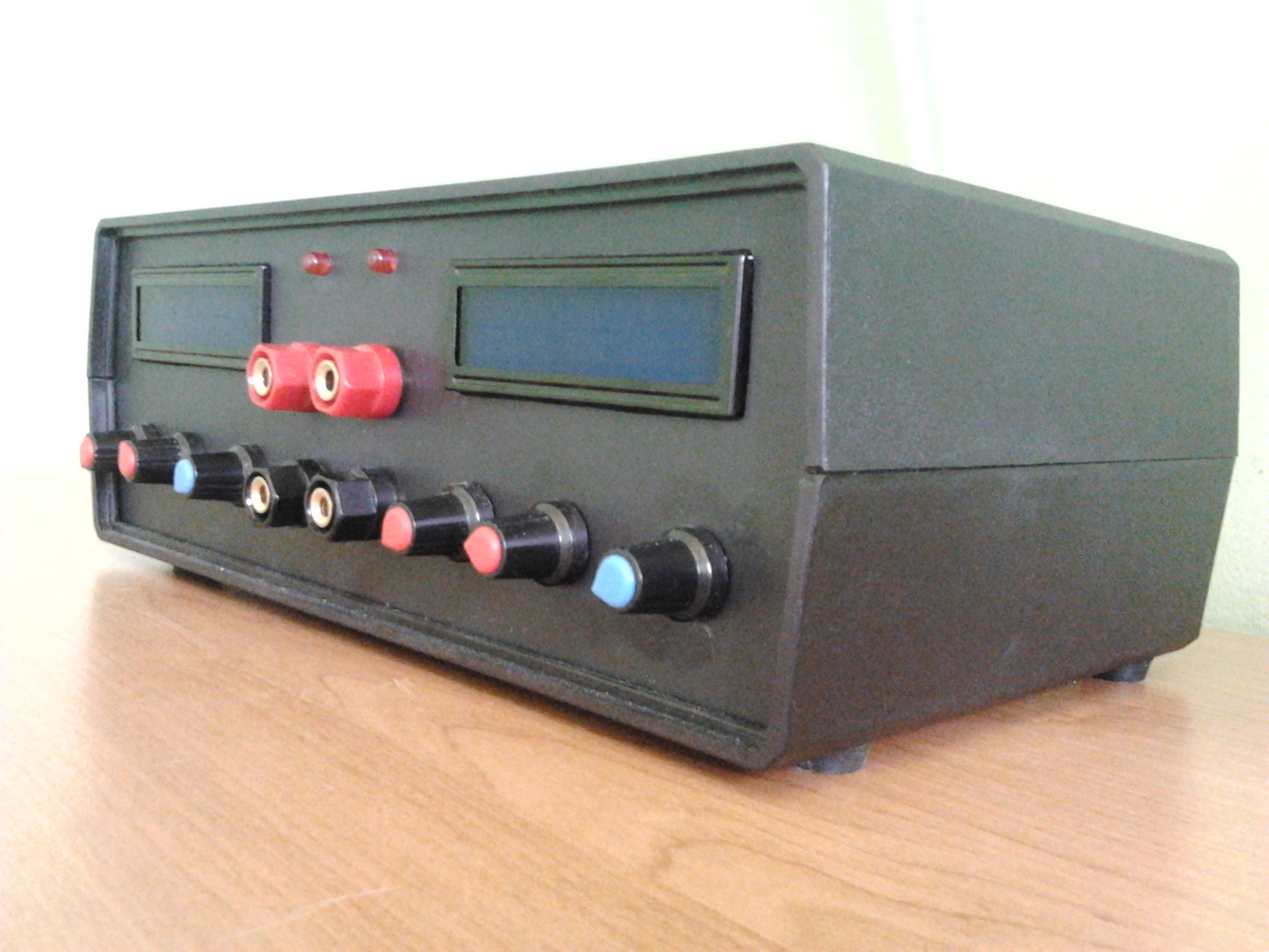
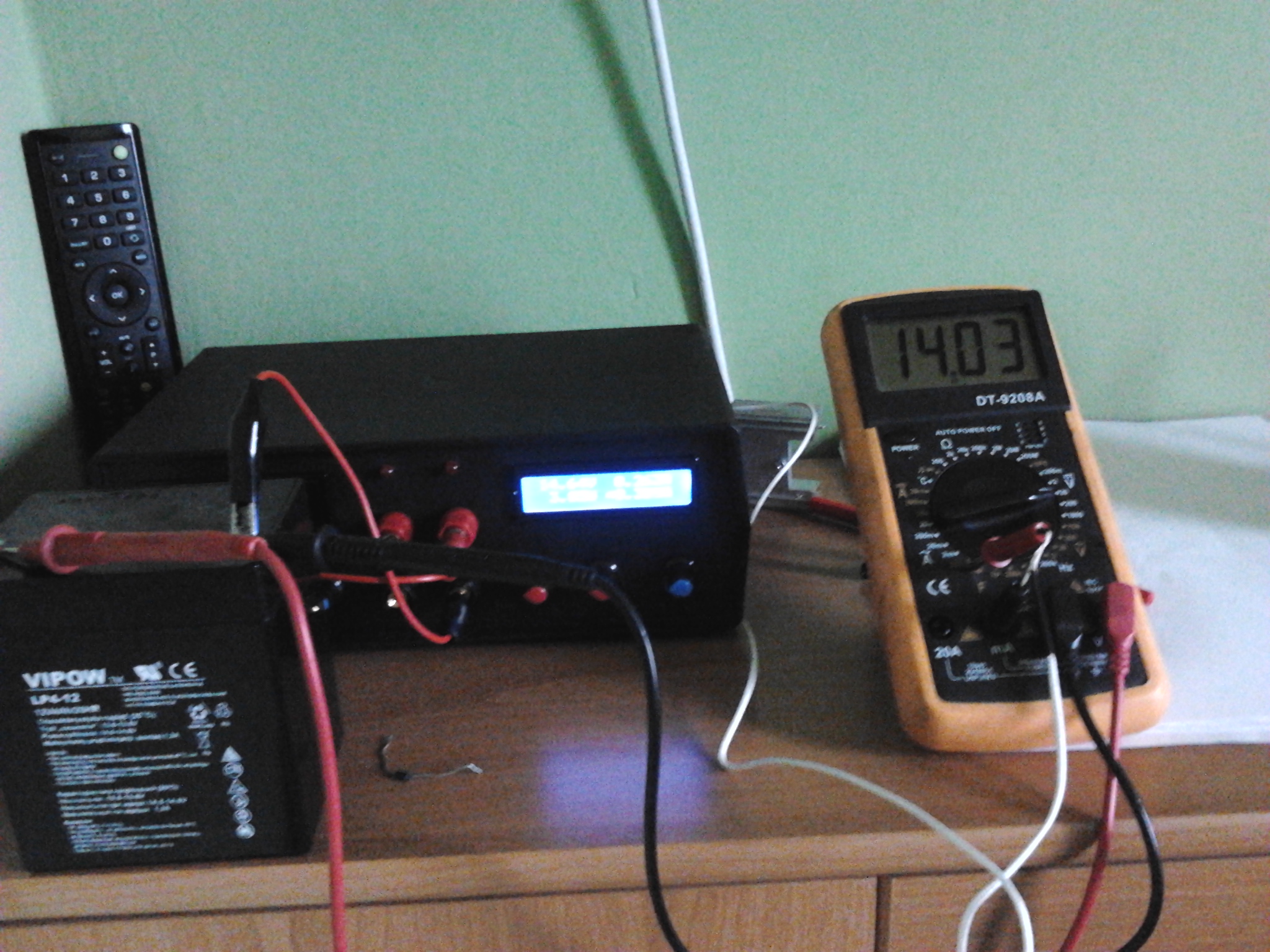
It is a design of double lab power supply, useful in such a situation when your work requires two different voltages to power the circuits.
Construction:
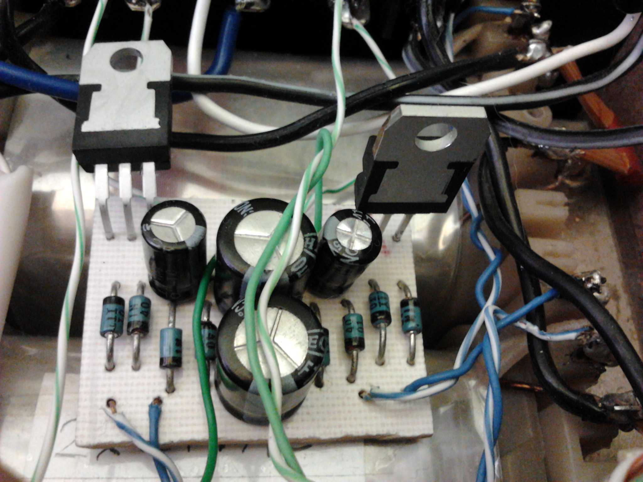
The power supply is based on very good in terms of quality and price, well-known schematic from: HERE.
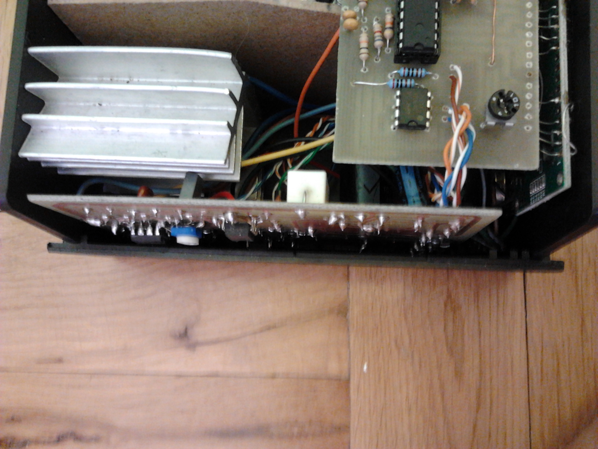
Transistors were changed from Q2 1n2219 to BD 139, but you can use those recommended in the original schematic. All PCBs can be home made in thermal transfer method.
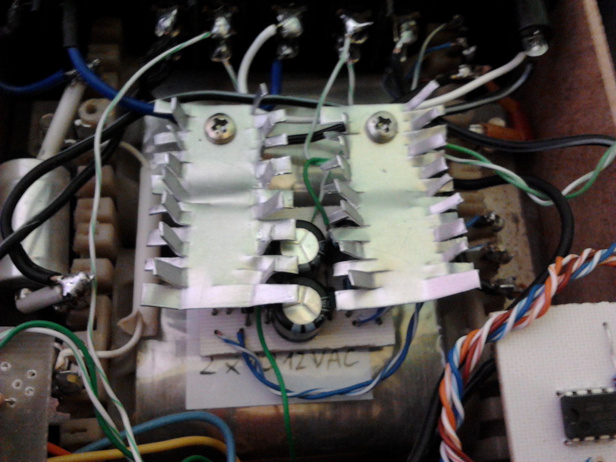
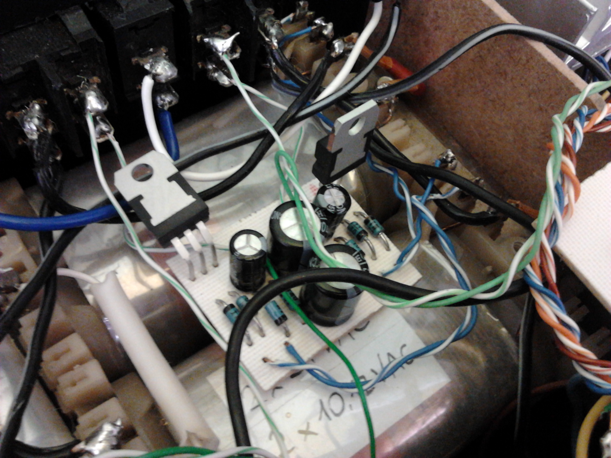
Transformer used in this project was removed from an old device, it has 4 windings, 2 x 22V (rectified, it is max 27V) and 2 x winding used to power the meters (they were 22V winded with a thin wire, but for the purpose of the meters it was enough, so that you can rewind some until you have 10V AC, 12V DC rectified – L7805 stabilized to 5V meters power supply).
Meters are also home made. At THIS page you can find more information about them.
Plastic housing is cheaper, easier and safer to be made than a metal one. In this project it is Z-15 housing.
There are two potentiometers for voltage control of one power supply (rough and precise), although the rough uses 2,2K, which can be easily replaced with 1K.
Rough control is enough to control current.
Sockets/clamps are golden, screwed or for banana plug.
The diodes indicating the current limitation are red blinking diodes, they act very well as indicators.
Heat sinks for transistors 2N3055 should be a little bigger (heat sinks visible inside the housing, outside it smaller flat heat sinks were screwed on 1 copper screw, which are used for feel the heat sink temperature inside with your hand). Silicone pads and thermo-conductive paste type H were used under 2N3055.
Pictures:


And video:
Link to original thread (useful attachment) - Podwójny zasilacz warsztatowy 2x 0-28V 2mA-3A