libbresse
Newbie level 6
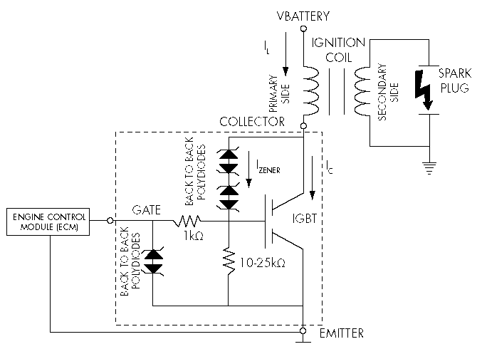
igbt ignition circuit
I want to build a distributor to my ignitionsystem in my dragrace snowmobile.
Would like to have input on the sketch I have done if it is good enough or if I should build it different.
circuit:
**broken link removed**
coil driver:
http://search.digikey.com/scripts/DkSearch/dksus.dll?Detail&name=IRGSL14C40LPBF-ND
 I have changed the circuit by your scheme.