Continue to Site

Welcome to EDAboard.com

Welcome to our site! EDAboard.com is an international Electronics Discussion Forum focused on EDA software, circuits, schematics, books, theory, papers, asic, pld, 8051, DSP, Network, RF, Analog Design, PCB, Service Manuals... and a whole lot more! To participate you need to register. Registration is free. Click here to register now.

current limit in buck converter

Status
Not open for further replies.

yoosefheidari

Member level 5
Member level 5
Joined
Aug 31, 2013
Messages
91
Helped
0
Reputation
0
Reaction score
1
Trophy points
1,288
Activity points
2,051
hi guys
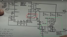
i saw in many commercial modules(buck-boost-etc...) for current limit section they use an op-amp and connect it to FB pin of controller.
but why they didn't use controller;s built-in current limit op-amp?just connect two sides of shunt resistor to current sense pins and then no need to extra op-amp or other circuits and even it costs less!
is there any disadvantage of using controller's current sesnse section? or any advantage of using external op-amp and connect it to FB pin of controller(actually using voltage feedback to limit current)?
Untitled.jpg
 

Hi,

I haven't had a close look at the datasheet, but it mentions that the LM25116 [1] is most efficient for output currents of 2 A. Whereas in the lower right, a current range of 0 to 20 A is indicated. You would have to calculate the required variable resitance to cover 0 to 20 A, by the use of the current limiting function of the IC. Keep in mind, if you are using the current sensing pins, this variable resistor potentiometer, will also pass the 20 A. Would be interesting how much a such a potentiometer costs. Furter, by assuming A is 10 (section 7.3.7 in the DS) and you want to set the current limit to 20 A, you would need a potentiometer setting resistor of 6.1 mΩ. Which you will hardly achive with a potentiometer, due to its residual resitance [2].

BTW, is there an actual Vout-, it looks like the positive input of the LM321 is tied to GND by the 40 mΩ resistor.

[1] https://www.ti.com/lit/ds/symlink/lm25116.pdf
[2] https://tech.alpsalpine.com/e/products/faq/potentiometer/features.html

BR
 
Hi,

The current limit pin is for "low side cycle by cycle current limit", it is not the output current.

Klaus
 
Yes, and where they connect the inner loop current sense is the "wrong" place....as it senses the current when the upper fet is off.......but this LM25116 module uses "emulated current mode control"....so it cleverly reconstructs the current ramp.....magically, as if it was actually sensing the current in the upper fet.............
This is good as it means you can have very very small on times and not have to worry about leading edge blanking time beiong longer than the on time.

But yes Klau sis correct..........that current sense in pin 13 is for inner current loop control.......look up "current mode control" and you will realise.

This course has a section on it...i think its in the "control modes folder" of the "small folders".

SMPS course_Big folders

https://drive.google.com/file/d/17ij_pQLkAzzYeL_TRNci86sXHMirKHmD/view?usp=sharing

SMPS course_little folders

https://drive.google.com/file/d/1WvElhDNfHI0EBei4rouSNEdWWTO1oCtJ/view?usp=sharing
 
Status
Not open for further replies.

Similar threads

Part and Inventory Search

Welcome to EDABoard.com

Sponsor

Back
Top