rafi8112
Newbie
Hello all users!
I designed this project three years ago - but only now I decided to present it on a foreign forum.
The link to the original source is here:
https://www.elektroda.pl/rtvforum/topic3723318.html
I would like to present a working project on which I spent roughly five and a half years, or more precisely, about 6000 hours.
One day in May 2014, I felt an incomparable desire to learn the exact principle of operation of a rather trivial piece of equipment, which is a calculator. It seems to be a simple device and so obvious that it's a shame to dwell on it...
At first glance, you can really say that, but is it so obvious?
I remember that the first night was sleepless - I was disturbed by thoughts that crowded in my head trying to grasp the principle of operation of this very common device. I thought that over time, this unrestrained exploration of secret knowledge would evaporate on its own, but nothing could be further from the truth...
I began to wonder more and more how to build at least a four-function calculator from basic logic bricks without using any advanced integrated circuit. For the first weeks I had various ideas and came up with more and more advanced solutions.
I started searching the internet, first Polish websites, forums, etc. I didn't come across anything but one small project:
https://www.elektroda.pl/rtvforum/topic2456401.html
There were many questions about the construction of such a calculator, but the answers of other users did not bring anything specific either.
I went a step further and searched the world's internet - it was much more interesting here, there are pages devoted to the history of electronic calculators - very extensive anyway. Due to the fact that I do not know English, I translated with Google Translate into our native language. Analyzing the content of these pages, I learned a lot about these devices - I was surprised that there were even tube versions, and later on hundreds of transistors and diodes. I was amazed by the ingenuity of the engineers of the time, and I was amazed that these prehistoric machines worked at all. I also came across calculators made of integrated circuits with a smaller scale of integration, I found diagrams, service manuals and manuals for them, and on some websites there were their simulators. I call myself a bull's-eye, but nothing could be more wrong ... The diagrams were very illegible, unintuitive and generally very confusing, each calculator had its own original operation specifics, so even if I managed to completely recreate the exact principle of operation of one of these calculators, and then "reconstruct" to the specificity of modern basic integrated circuits - I would not feel satisfied and in my opinion I would have committed plagiarism.
It was a little easier with the analysis of algorithms of mathematical operations - here too there were quite peculiar nomenclature and symbolism, and due to the fact that I have never used a microprocessor in any of my projects in my life, and I have practically no idea about programming - I had to learn all these operands, basic shifts bits, jumps, increments and decrements of counters and many, many others. The simulators of these old calculators turned out to be quite helpful - thanks to that, every day I learned how to cleverly combine them to finally create my original machine language, and then implement it to my own processor built of basic logic bricks. I have to admit that some of the calculator simulators were so well made that they even contained the original calculation errors of these machines. Another challenge arose - improving them ... Finally, I succeeded, and I gained some more experience. After analyzing several simulators - I finally decided to create counting algorithms that I will use in my device. As part of consolidating my knowledge, I wrote them down very carefully on hundreds of sheets and, using the dependencies, I counted mathematical tasks dry. While carrying out all these operations, I built diagrams for each action. At the same time, I changed and improved a lot, and also eliminated the original bugs.
In the meantime, I was also developing hardware circuits that became more and more complex. I decided on the TTL family circuits because I have a fondness for them - in elementary school, being in the sixth grade, I wanted to construct a robot using these circuits, the construction took me almost two years and turned out to be a complete failure, among others, because the logical one at the input is after all, the same as the input not connected to anything - I didn't know it then")
As I wrote above, at the very beginning I wanted to construct "only" a four-function calculator, but the project grew a bit - I added: square root, square power, division by inverse and percentage operations, also after further consideration the device received the ability to display the PI number, additional memory M, copying the result to the active input register, cross-replacement of arguments, undoing the entered values and comprehensive handling of negative numbers.
Month after month passed, I was constantly designing the control logic that was supposed to understand my machine language, more and more voluminous documentation was created where I tried to note and describe everything.
When I had most of the part designed, my dear friend from Warsaw, Mr. Piekarski, suggested that I add a diagnostic function to this device - after thinking about it, I really liked this idea, although it consumed an additional almost 100 integrated circuits ...
Once I had everything ready on "paper", I began to thoroughly analyze every circuit of the device, every connection and every dependency between the modules (initially, at that time, I divided the device into 30 modules) and the instructions of the algorithms that "powered" the logic of the calculator. It took me almost 9 consecutive months, but thanks to this I eliminated about 30 errors that were more or less important in the work of the future project. In parallel with all this, I also started designing tiles in the first version, it was supposed to be 6 double-sided tiles with a total area of about 1.5 m2. Thanks to this, I gained another experience in manual PCB design. Over time, it turned out that the double-sided plates are not very effective in relation to the required density of elements, believe me, I really stretched myself by running several thousand paths, including thousands of vias. Unfortunately, I was sniffing out problems more and more because the connections were getting too long, and there was simply no room for signal conditioning elements, my intuition told me to abandon this idea of using double-sided laminates anyway. And so a few months of work went ...
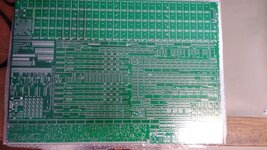
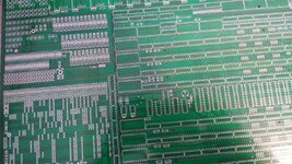
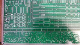
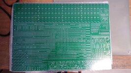
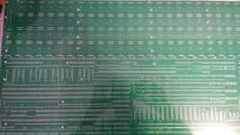
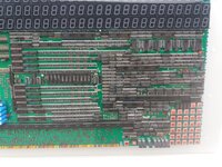
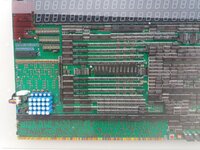
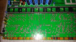
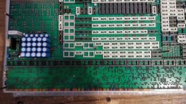
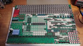
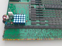
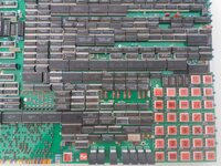
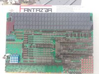
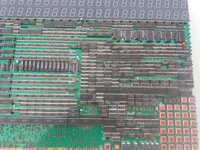
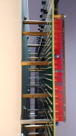
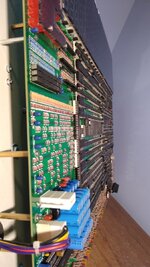
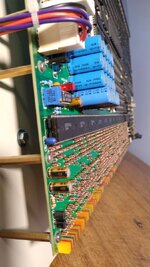
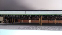
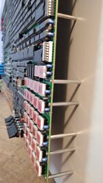
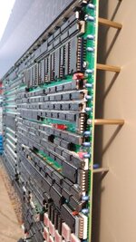
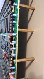
However, nothing is lost, I knew what "skeleton" of this device I had to create, I saw it all in my imagination - I went all out and decided to use an eight-layer board - its dimensions had to be at least 66 by 46 centimeters - that was the first assumption. I started designing such a tile, it took me another few months, in fact I still didn't like something and I was never completely satisfied, but in the end I had to finish it - its final size is 72 by 50 centimeters. Now it was enough to produce it ... Initially, a year earlier, I talked about this matter with a company from Gdańsk, which was the only one of all the companies in Poland to which I sent inquiries that was able to undertake the production of such a large plate, of course cooperating with a factory in China. I had no choice but to send the Gerberas of this project to this company. The best was in a few hours when I was going through my inbox - I got an e-mail that they would not take on this task because with one piece I would give up anyway due to the huge cost. I thought I would drop to the ground right away, my heart started pounding like crazy - being at the very end of this terribly long road, someone poured a bucket of cold water over my head. Don't ask me what was going on when I called the company, trying to "gently" talk about the situation... Fortunately, I convinced them that I would pay them the expected high amount and finally the Chinese had something to do... The CD reached me about a month after placing it order, I remember the night before her arrival - I had dreams that there are transparent layers on it, and that it has a much smaller dimension, etc. However, to my great joy, the next day the disc arrived as it should be, I could not be amazed at the precision of workmanship in such a large area. I finally started the assembly, which took almost three months - I also had to bend quite a lot, a board of this size, even 2mm thick, after soldering many thousands of elements, was very unstable, it became very heavy, it had to be handled better than an egg . It's good that I used several dozen M2 and M3 spacers in the mounting holes, which helped a bit and kept the board in check.
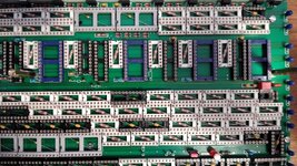
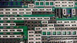
When I had soldered all the elements, more precisely, several thousand through-hole elements, I started to assemble integrated circuits to the sockets, creating device modules from them. I launched and tested more and more modules - with such a large project it is necessary to run sequentially to detect possible irregularities. It was January 1, 2020, the day after my 38th birthday, around 3:30 am, I had three most complicated modules left to run - I took a great risk - I installed the remaining dozens of systems and launched the device comprehensively. I began to check them more and more carefully, more and more tests brought positive results. After a comprehensive check, I knew that there were some bugs that I would have to eliminate, but it was almost dawn, so I went to sleep. Errors turned out to be of a smaller and larger caliber. I eliminated them for the next month, the worst error was related to the square root - here I really had to spend a lot of time to eliminate it, the irony was that on paper I was doing a simulation of counting the square root of two, and this error concerned, among others, the square root of the number 3. Over the years I have dreamed many times that there is something wrong with this element - reality only confirmed it...
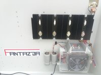
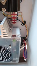
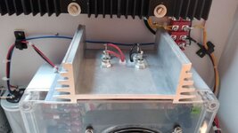
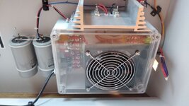
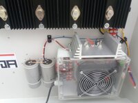
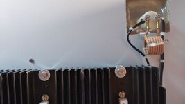
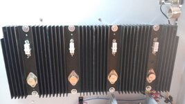
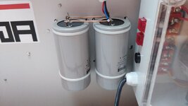
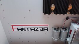
After the successful elimination of all errors, it was time to disconnect the laboratory power supply and connect the newly constructed power supply for this device, and here it was not without a mistake - I ordered a transformer with a slightly too low nominal voltage, I wanted to reduce power on the transistors of the linear stabilizer as little as possible. Routine got me lost and I couldn't recover the 1.5V that got reduced on diodes, wires and other "lossy" components along the way. Another irony of fate
I ordered a second transformer with a higher voltage and finally the power supply started working properly, the calculator is powered by only one voltage +5V. During operation, it consumes about 12A of electricity.
In short:
The processor of the device interprets 59 instructions, each instruction may contain from one to a dozen executive functions, which can be blocked with one of the 40 conditional functions.
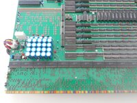
Up to 396-bit RAM based on 99 four-bit shift registers 74LS194
The ROM is 3840 bits, it is a diode memory with an organization of 16 by 240
The digit input registers A and B and memory register M are 12 digits
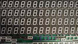
The result register W is 24 digits long
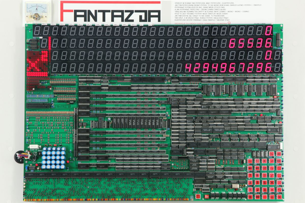
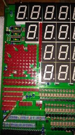
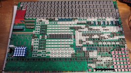
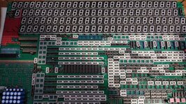
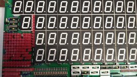
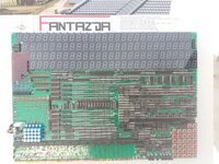
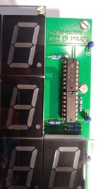
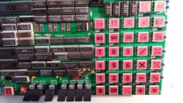
The device has 105 LED displays, where 65 of them are working displays, while the rest are used in the diagnostic mode, 33 keyboard buttons are backlit and respond to several dependencies in real time.
The calculator has 400 LEDs that are used for various purposes in standard and diagnostic mode.
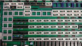
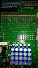
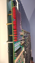
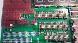
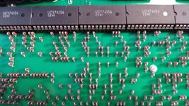
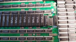
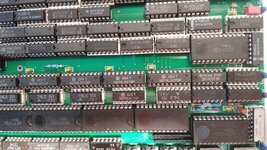
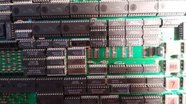
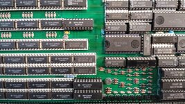
In addition, the device includes: 477 integrated circuits and the same number of sockets, 370 resistors, 7 ladders, 165 capacitors, 1678 switching diodes, 270 transistors and several other electronic components.
There are 15 algorithms in ROM:
- DIG (entering digits from 0 to 9 or the string 00 into the active register)
- MS (copy active register to M register)
- MR (copying the M register to the active register)
- WRC (transfer of the contents of the W register to the active register)
- AB (cross replacement of the contents of registers A and B)
- BK (retraction of the last entered digit in the active register)
- PI (loading the number of PI to the active register)
- ADD/SUB (arithmetic addition or subtraction of registers A and B)
- MUL (arithmetic multiplication of registers A and B)
- DIV (arithmetic division of registers A and B)
- SQRT (square root of the active register)
- X2 (squaring active register)
- 1/X (divide by the inverse of the active register)
- +%-% (transfer of the content of the W register containing the result of the operation: [(B/100)*A] to the B register)
- ACW (positioning to the right of the result in the W register by getting rid of unnecessary zeros on the left and right).
All the above algorithms except: MUL, DIV and SQRT are my own. I suggested the algorithms: MUL, DIV and SQRT in the simulators of old calculators, probably from CASIO, but I had to fix them, remake them so that they were digestible for the logic of my device. On the other hand, I think that these three algorithms are very obvious for people dealing with professional programming and there is nothing groundbreaking in them.
The machine language and all instructions contained therein are my own.
The control logic that creates all the modules and circuits in the device is invented by me.
The calculator is a device 100% invented and built by me - no third parties participated in the project.
Below is the address to three videos presenting the device in more detail:
https://drive.google.com/drive/folders/1OtaiIVUoTU29yrk9m-f7NktsKwMqPHvK?usp=sharing
Link to the videos - unfortunately of poorer quality can be found here:
https://www.youtube.com/@rafalwisniewskiTTL
You can read a bit about me here:
https://pl.linkedin.com/in/rafał-wiśniewski-20b469215
A little more technical about the device:
https://elportal.pl/projekty/hobbyp/446-kalkulator-ttl-czesc-1-schemat-montaz-opis-ukladu
https://elportal.pl/projekty/hobbyp/464-kalkulator-ttl-czesc-2-omowienie-modulow
Photos:
I designed this project three years ago - but only now I decided to present it on a foreign forum.
The link to the original source is here:
https://www.elektroda.pl/rtvforum/topic3723318.html
I would like to present a working project on which I spent roughly five and a half years, or more precisely, about 6000 hours.
One day in May 2014, I felt an incomparable desire to learn the exact principle of operation of a rather trivial piece of equipment, which is a calculator. It seems to be a simple device and so obvious that it's a shame to dwell on it...
At first glance, you can really say that, but is it so obvious?
I remember that the first night was sleepless - I was disturbed by thoughts that crowded in my head trying to grasp the principle of operation of this very common device. I thought that over time, this unrestrained exploration of secret knowledge would evaporate on its own, but nothing could be further from the truth...
I began to wonder more and more how to build at least a four-function calculator from basic logic bricks without using any advanced integrated circuit. For the first weeks I had various ideas and came up with more and more advanced solutions.
I started searching the internet, first Polish websites, forums, etc. I didn't come across anything but one small project:
https://www.elektroda.pl/rtvforum/topic2456401.html
There were many questions about the construction of such a calculator, but the answers of other users did not bring anything specific either.
I went a step further and searched the world's internet - it was much more interesting here, there are pages devoted to the history of electronic calculators - very extensive anyway. Due to the fact that I do not know English, I translated with Google Translate into our native language. Analyzing the content of these pages, I learned a lot about these devices - I was surprised that there were even tube versions, and later on hundreds of transistors and diodes. I was amazed by the ingenuity of the engineers of the time, and I was amazed that these prehistoric machines worked at all. I also came across calculators made of integrated circuits with a smaller scale of integration, I found diagrams, service manuals and manuals for them, and on some websites there were their simulators. I call myself a bull's-eye, but nothing could be more wrong ... The diagrams were very illegible, unintuitive and generally very confusing, each calculator had its own original operation specifics, so even if I managed to completely recreate the exact principle of operation of one of these calculators, and then "reconstruct" to the specificity of modern basic integrated circuits - I would not feel satisfied and in my opinion I would have committed plagiarism.
It was a little easier with the analysis of algorithms of mathematical operations - here too there were quite peculiar nomenclature and symbolism, and due to the fact that I have never used a microprocessor in any of my projects in my life, and I have practically no idea about programming - I had to learn all these operands, basic shifts bits, jumps, increments and decrements of counters and many, many others. The simulators of these old calculators turned out to be quite helpful - thanks to that, every day I learned how to cleverly combine them to finally create my original machine language, and then implement it to my own processor built of basic logic bricks. I have to admit that some of the calculator simulators were so well made that they even contained the original calculation errors of these machines. Another challenge arose - improving them ... Finally, I succeeded, and I gained some more experience. After analyzing several simulators - I finally decided to create counting algorithms that I will use in my device. As part of consolidating my knowledge, I wrote them down very carefully on hundreds of sheets and, using the dependencies, I counted mathematical tasks dry. While carrying out all these operations, I built diagrams for each action. At the same time, I changed and improved a lot, and also eliminated the original bugs.
In the meantime, I was also developing hardware circuits that became more and more complex. I decided on the TTL family circuits because I have a fondness for them - in elementary school, being in the sixth grade, I wanted to construct a robot using these circuits, the construction took me almost two years and turned out to be a complete failure, among others, because the logical one at the input is after all, the same as the input not connected to anything - I didn't know it then
As I wrote above, at the very beginning I wanted to construct "only" a four-function calculator, but the project grew a bit - I added: square root, square power, division by inverse and percentage operations, also after further consideration the device received the ability to display the PI number, additional memory M, copying the result to the active input register, cross-replacement of arguments, undoing the entered values and comprehensive handling of negative numbers.
Month after month passed, I was constantly designing the control logic that was supposed to understand my machine language, more and more voluminous documentation was created where I tried to note and describe everything.
When I had most of the part designed, my dear friend from Warsaw, Mr. Piekarski, suggested that I add a diagnostic function to this device - after thinking about it, I really liked this idea, although it consumed an additional almost 100 integrated circuits ...
Once I had everything ready on "paper", I began to thoroughly analyze every circuit of the device, every connection and every dependency between the modules (initially, at that time, I divided the device into 30 modules) and the instructions of the algorithms that "powered" the logic of the calculator. It took me almost 9 consecutive months, but thanks to this I eliminated about 30 errors that were more or less important in the work of the future project. In parallel with all this, I also started designing tiles in the first version, it was supposed to be 6 double-sided tiles with a total area of about 1.5 m2. Thanks to this, I gained another experience in manual PCB design. Over time, it turned out that the double-sided plates are not very effective in relation to the required density of elements, believe me, I really stretched myself by running several thousand paths, including thousands of vias. Unfortunately, I was sniffing out problems more and more because the connections were getting too long, and there was simply no room for signal conditioning elements, my intuition told me to abandon this idea of using double-sided laminates anyway. And so a few months of work went ...
However, nothing is lost, I knew what "skeleton" of this device I had to create, I saw it all in my imagination - I went all out and decided to use an eight-layer board - its dimensions had to be at least 66 by 46 centimeters - that was the first assumption. I started designing such a tile, it took me another few months, in fact I still didn't like something and I was never completely satisfied, but in the end I had to finish it - its final size is 72 by 50 centimeters. Now it was enough to produce it ... Initially, a year earlier, I talked about this matter with a company from Gdańsk, which was the only one of all the companies in Poland to which I sent inquiries that was able to undertake the production of such a large plate, of course cooperating with a factory in China. I had no choice but to send the Gerberas of this project to this company. The best was in a few hours when I was going through my inbox - I got an e-mail that they would not take on this task because with one piece I would give up anyway due to the huge cost. I thought I would drop to the ground right away, my heart started pounding like crazy - being at the very end of this terribly long road, someone poured a bucket of cold water over my head. Don't ask me what was going on when I called the company, trying to "gently" talk about the situation... Fortunately, I convinced them that I would pay them the expected high amount and finally the Chinese had something to do... The CD reached me about a month after placing it order, I remember the night before her arrival - I had dreams that there are transparent layers on it, and that it has a much smaller dimension, etc. However, to my great joy, the next day the disc arrived as it should be, I could not be amazed at the precision of workmanship in such a large area. I finally started the assembly, which took almost three months - I also had to bend quite a lot, a board of this size, even 2mm thick, after soldering many thousands of elements, was very unstable, it became very heavy, it had to be handled better than an egg . It's good that I used several dozen M2 and M3 spacers in the mounting holes, which helped a bit and kept the board in check.
When I had soldered all the elements, more precisely, several thousand through-hole elements, I started to assemble integrated circuits to the sockets, creating device modules from them. I launched and tested more and more modules - with such a large project it is necessary to run sequentially to detect possible irregularities. It was January 1, 2020, the day after my 38th birthday, around 3:30 am, I had three most complicated modules left to run - I took a great risk - I installed the remaining dozens of systems and launched the device comprehensively. I began to check them more and more carefully, more and more tests brought positive results. After a comprehensive check, I knew that there were some bugs that I would have to eliminate, but it was almost dawn, so I went to sleep. Errors turned out to be of a smaller and larger caliber. I eliminated them for the next month, the worst error was related to the square root - here I really had to spend a lot of time to eliminate it, the irony was that on paper I was doing a simulation of counting the square root of two, and this error concerned, among others, the square root of the number 3. Over the years I have dreamed many times that there is something wrong with this element - reality only confirmed it...
After the successful elimination of all errors, it was time to disconnect the laboratory power supply and connect the newly constructed power supply for this device, and here it was not without a mistake - I ordered a transformer with a slightly too low nominal voltage, I wanted to reduce power on the transistors of the linear stabilizer as little as possible. Routine got me lost and I couldn't recover the 1.5V that got reduced on diodes, wires and other "lossy" components along the way. Another irony of fate
I ordered a second transformer with a higher voltage and finally the power supply started working properly, the calculator is powered by only one voltage +5V. During operation, it consumes about 12A of electricity.
In short:
The processor of the device interprets 59 instructions, each instruction may contain from one to a dozen executive functions, which can be blocked with one of the 40 conditional functions.
Up to 396-bit RAM based on 99 four-bit shift registers 74LS194
The ROM is 3840 bits, it is a diode memory with an organization of 16 by 240
The digit input registers A and B and memory register M are 12 digits
The result register W is 24 digits long
The device has 105 LED displays, where 65 of them are working displays, while the rest are used in the diagnostic mode, 33 keyboard buttons are backlit and respond to several dependencies in real time.
The calculator has 400 LEDs that are used for various purposes in standard and diagnostic mode.
In addition, the device includes: 477 integrated circuits and the same number of sockets, 370 resistors, 7 ladders, 165 capacitors, 1678 switching diodes, 270 transistors and several other electronic components.
There are 15 algorithms in ROM:
- DIG (entering digits from 0 to 9 or the string 00 into the active register)
- MS (copy active register to M register)
- MR (copying the M register to the active register)
- WRC (transfer of the contents of the W register to the active register)
- AB (cross replacement of the contents of registers A and B)
- BK (retraction of the last entered digit in the active register)
- PI (loading the number of PI to the active register)
- ADD/SUB (arithmetic addition or subtraction of registers A and B)
- MUL (arithmetic multiplication of registers A and B)
- DIV (arithmetic division of registers A and B)
- SQRT (square root of the active register)
- X2 (squaring active register)
- 1/X (divide by the inverse of the active register)
- +%-% (transfer of the content of the W register containing the result of the operation: [(B/100)*A] to the B register)
- ACW (positioning to the right of the result in the W register by getting rid of unnecessary zeros on the left and right).
All the above algorithms except: MUL, DIV and SQRT are my own. I suggested the algorithms: MUL, DIV and SQRT in the simulators of old calculators, probably from CASIO, but I had to fix them, remake them so that they were digestible for the logic of my device. On the other hand, I think that these three algorithms are very obvious for people dealing with professional programming and there is nothing groundbreaking in them.
The machine language and all instructions contained therein are my own.
The control logic that creates all the modules and circuits in the device is invented by me.
The calculator is a device 100% invented and built by me - no third parties participated in the project.
Below is the address to three videos presenting the device in more detail:
https://drive.google.com/drive/folders/1OtaiIVUoTU29yrk9m-f7NktsKwMqPHvK?usp=sharing
Link to the videos - unfortunately of poorer quality can be found here:
https://www.youtube.com/@rafalwisniewskiTTL
You can read a bit about me here:
https://pl.linkedin.com/in/rafał-wiśniewski-20b469215
A little more technical about the device:
https://elportal.pl/projekty/hobbyp/446-kalkulator-ttl-czesc-1-schemat-montaz-opis-ukladu
https://elportal.pl/projekty/hobbyp/464-kalkulator-ttl-czesc-2-omowienie-modulow
Photos:
Attachments
-
 4203020200_1598228330.jpg190.2 KB · Views: 79
 -
 4789551800_1598228351.jpg237.1 KB · Views: 79
 -
 9900040300_1598228353.jpg200.8 KB · Views: 75
 -
 3174053500_1598228368.jpg155.2 KB · Views: 76
 -
 8752891800_1598228389.jpg173.6 KB · Views: 73
 -
 4657719900_1598228482.jpg206 KB · Views: 78
 -
 8311916900_1598228482.jpg225.5 KB · Views: 76
 -
 9471225000_1598228497.jpg197.3 KB · Views: 78
 -
 3786279900_1598228497.jpg187.8 KB · Views: 70
 -
 2788850400_1598228653.jpg186.3 KB · Views: 81
 -
 3285252500_1598228671.jpg215.7 KB · Views: 87
 -
 8991005300_1598229021.jpg76.1 KB · Views: 71
 -
 3304920300_1598229024.jpg231.6 KB · Views: 71
 -
 8297310900_1598229000.jpg241.6 KB · Views: 79
 -
 6149140600_1598228695.jpg184.2 KB · Views: 77
 -
 8207265900_1598228696.jpg236.2 KB · Views: 76
 -
 4604512600_1598228679.jpg247.8 KB · Views: 78
 -
 4396850400_1598228674.jpg224.3 KB · Views: 80
 -
 4219671600_1598228651.jpg170 KB · Views: 77
 -
 1870480700_1598228653.jpg181.5 KB · Views: 70
 -
 3474329100_1598229076.jpg196.6 KB · Views: 77
 -
 6425975100_1598912029.jpg82.4 KB · Views: 87
 -
 8700237800_1598912024.jpg83.7 KB · Views: 74
 -
 2009987700_1598912018.jpg93.9 KB · Views: 71
 -
 4015898700_1598229077.jpg225.8 KB · Views: 68
 -
 9731022100_1598229047.jpg200.5 KB · Views: 82
 -
 5834682300_1598229043.jpg161.7 KB · Views: 73
 -
 7005934500_1598229046.jpg235.1 KB · Views: 76
 -
 1327905500_1598229022.jpg92.1 KB · Views: 72
 -
 7666050200_1598229071.jpg247.4 KB · Views: 82
 -
 7714792900_1598912120.jpg102 KB · Views: 76
 -
 7308802600_1598912156.jpg79.1 KB · Views: 78
 -
 4883420700_1598912124.jpg133.2 KB · Views: 72
 -
 9352466000_1598912121.jpg119.4 KB · Views: 73
 -
 8303572700_1598912087.jpg64.9 KB · Views: 79
 -
 7213787800_1598912082.jpg59.7 KB · Views: 71
 -
 9863662300_1598912063.jpg89.7 KB · Views: 71
 -
 9446122000_1598912055.jpg75.1 KB · Views: 73
 -
 3616260300_1598912055.jpg66.3 KB · Views: 77
 -
 9753561700_1598912084.jpg58.5 KB · Views: 79
 -
 9905071300_1598912152.jpg84.4 KB · Views: 70
 -
 9797214400_1598912168.jpg163.7 KB · Views: 71
 -
 3916341600_1598912193.jpg118.4 KB · Views: 76
 -
 2075220700_1598912210.jpg174.9 KB · Views: 77
 -
 3646148500_1598912233.jpg195.9 KB · Views: 80
 -
 3939089400_1598912237.jpg160.4 KB · Views: 83
 -
 8637207800_1598912251.jpg160.7 KB · Views: 78
 -
 5325636300_1598912299.jpg193.6 KB · Views: 80
 -
 7068288900_1598912282.jpg96.4 KB · Views: 71
 -
 6058340700_1598912296.jpg125.2 KB · Views: 89
 -
 8252203000_1598912309.jpg87.6 KB · Views: 72
 -
 9306320800_1598448479.png672.5 KB · Views: 94
Last edited:
