Continue to Site

Welcome to EDAboard.com

Welcome to our site! EDAboard.com is an international Electronics Discussion Forum focused on EDA software, circuits, schematics, books, theory, papers, asic, pld, 8051, DSP, Network, RF, Analog Design, PCB, Service Manuals... and a whole lot more! To participate you need to register. Registration is free. Click here to register now.

Comparing different Sensors using opamps

Status
Not open for further replies.

shemo

Advanced Member level 4
Joined
Apr 26, 2002
Messages
105
Helped
0
Reputation
0
Reaction score
0
Trophy points
1,296
Activity points
709
opamp.PNG

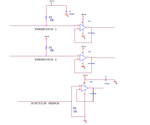
I have this circuit diagram.
Thermistor1, themistor2, and position sensor.

A few questions.
1)Why thermistor1 pulled up to 5V? versus position sensor which pulled down using 1M resistor?

2)Why thermistor1 has a cap from 5V to GND and thermistor1 doesn't?

3)Because the output doesn't have a resistor load, and direct feedback from negative of opamp to output so the gain is 1?
 

Hi,

all opamps are voltage follower. That means at the output is the same voltage as on the input. BUT on the output of the opamps you can source/sink some mA without changing the voltage.
The voltages are stabilized.

1) Maybe it is needed by the sensor, (NTC, PTC, PT100, PT1000, diode, transistor...) or it is simply to recognize an unconnected sensor.

2) It´s just a block capacitor for 5V, and has nothing to do with thermistor 2

3) Yes, even with resistor load gain is 1
 

Hi,

all opamps are voltage follower. That means at the output is the same voltage as on the input. BUT on the output of the opamps you can source/sink some mA without changing the voltage.
The voltages are stabilized.

1) Maybe it is needed by the sensor, (NTC, PTC, PT100, PT1000, diode, transistor...) or it is simply to recognize an unconnected sensor.

If it's a voltage follower, then why need to use different pull-up versus pulldown on thermistor and position sensor. Why not just use pull-down for both? Since it's voltage follower, then it shouldn't matter right?
 

Hi,

you can see a thermistor as a simple resistor. If the thermistor is connected to GND (without a pullup) the opamap will allways see 0V. Independent of resistor value (temperature).

To measure the voltage (resitance, temperature) you need a current flowing trhough the thermistor. The simplest way to do this is to use a resistor as pullup.

Example: your thermistor has a resistance of 2.5k. Combined with the pullup of 10k you have 12.5k at 5V. Current then is 0.4 mA. 0.4mA at 2.5k = 1V.
This is the input of your opamp - and its output.

Why there is a pulldown and not a pullup at the position sensor depends on the position sensor and its inner electrical circuitry.

Show us what thermistor and position sensor is used and how it they are connected and we can help you better.

Klaus
 

View attachment 104539

I have this circuit diagram.
Thermistor1, themistor2, and position sensor.

A few questions.
1)Why thermistor1 pulled up to 5V? versus position sensor which pulled down using 1M resistor?

2)Why thermistor1 has a cap from 5V to GND and thermistor1 doesn't?

3)Because the output doesn't have a resistor load, and direct feedback from negative of opamp to output so the gain is 1?
1) thermistor1 pulled up to 5V because maybe the other end of thermistor is grounded . so that they form a voltage divider
2) it is good to use capacitor in all the three circuits and has nothing to do with thermistor 1,2,3
3) The opamps are used as Buffer unity gain to prevent loading of the thermistor

If you found this usefull do not forget to press the helped me button below
 

Status
Not open for further replies.

Similar threads

Part and Inventory Search

Welcome to EDABoard.com

Sponsor

Back
Top