sk78
Newbie level 1
I'm new to electronics and am responsible for developing the software for a data acquisition system. We have been working with an outside contractor for design guidance on the switching circuit but he is currently unavailable so I'm trying to pick up and run with the last few steps of the project.
The circuit is a straightforward signal switching design consisting of a couple of **broken link removed** 4>16 decoders and a 74HC238 to enable/disable them. The **broken link removed**decoders are driving a series of CPC104 SSRs. A USB data acquisition module from measurement computing (great products) providers the interface for my application to control the data bits for the decoders.
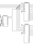
Here is the relevant section:
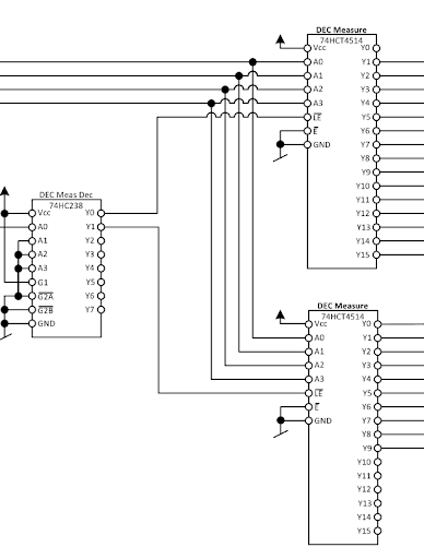
I have the circuit built up on a breadboard with SMT prototype boards for the SSRs and generally everything is working fine with one exception: The decoder is always enabled which means even when I pull all source pins down I'm still high on Y0. The problem is that only one SSR can be on at a time yet that's currently impossible (as I understand things) due to the fact the enable pin is hardwired to ground; as long as E is low then the output will be active. Again... I'm not an electronics guy (yet), so I could be way off but it looks like if I could invert the signal to E from LE I could achieve what I'm after. Basically, when the 74HC238 outputs H on Y0 it would pull down the E pin and pull up the LE pin on the first 74HCT4514. The same would happen on the second one when Y2 goes H and so on...
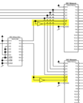
Here is a mockup of my proposed solution:
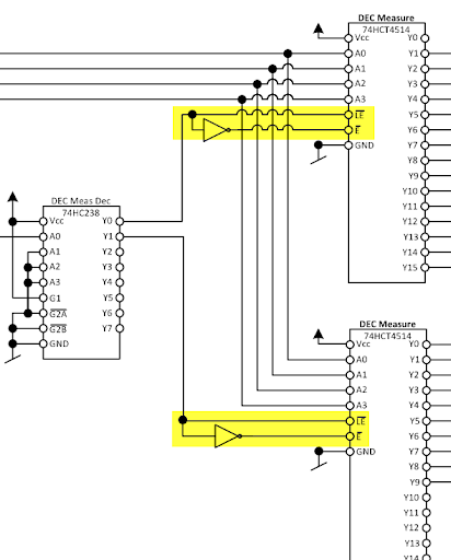
I've added the logical inverter symbol but honestly I don't know if there is an IC that will do what I want in that schematic? I suspect I need a transistor that would switch on the signal to LE and when active would pull E down. I also can't leave E floating, it needs to be up or down.
So as you can see I'm in over my head and I would REALLY appreciate input from anyone who understands what I'm trying to accomplish or can maybe tell me if my proposed solution would work. At this point it's just an idea, I have no idea how to take it to the next step.
Thanks for reading,
Steve
The circuit is a straightforward signal switching design consisting of a couple of **broken link removed** 4>16 decoders and a 74HC238 to enable/disable them. The **broken link removed**decoders are driving a series of CPC104 SSRs. A USB data acquisition module from measurement computing (great products) providers the interface for my application to control the data bits for the decoders.
Here is the relevant section:
I have the circuit built up on a breadboard with SMT prototype boards for the SSRs and generally everything is working fine with one exception: The decoder is always enabled which means even when I pull all source pins down I'm still high on Y0. The problem is that only one SSR can be on at a time yet that's currently impossible (as I understand things) due to the fact the enable pin is hardwired to ground; as long as E is low then the output will be active. Again... I'm not an electronics guy (yet), so I could be way off but it looks like if I could invert the signal to E from LE I could achieve what I'm after. Basically, when the 74HC238 outputs H on Y0 it would pull down the E pin and pull up the LE pin on the first 74HCT4514. The same would happen on the second one when Y2 goes H and so on...
Here is a mockup of my proposed solution:
I've added the logical inverter symbol but honestly I don't know if there is an IC that will do what I want in that schematic? I suspect I need a transistor that would switch on the signal to LE and when active would pull E down. I also can't leave E floating, it needs to be up or down.
So as you can see I'm in over my head and I would REALLY appreciate input from anyone who understands what I'm trying to accomplish or can maybe tell me if my proposed solution would work. At this point it's just an idea, I have no idea how to take it to the next step.
Thanks for reading,
Steve