Continue to Site

Welcome to EDAboard.com

Welcome to our site! EDAboard.com is an international Electronics Discussion Forum focused on EDA software, circuits, schematics, books, theory, papers, asic, pld, 8051, DSP, Network, RF, Analog Design, PCB, Service Manuals... and a whole lot more! To participate you need to register. Registration is free. Click here to register now.

Choice of amplifier front end...

Status
Not open for further replies.

Externet

Advanced Member level 2
Joined
Jan 29, 2004
Messages
579
Helped
28
Reputation
58
Reaction score
29
Trophy points
1,308
Location
Mideast US
Activity points
5,683
Hi.
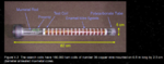
A ten thousand turn air core coil of 0.1mmΦ wire produces a faint signal from a distant slowly varying magnetic field; the signal to be amplified to move a galvanometer zero-centered pointer.
What type of amplifier or instrumentation amplifier is convenient (transistor or FET); Is it better to amplify the current or the voltage from the coil for highest sensitivity ?
Power supply can be 4V or ±4V.

Question two : The coil will be more sensitive to sense a slowly turning distant magnet if being long of small diametre, or short of large diametre ?

Question three : insertion of soft iron core changes answer to question two or not ?
 
Last edited:

The MOSFET transistor is recommended for applications where the electric charge flow is too small, so by the above specification, a circuit with FET input stage would be my preferred choice, although in the case of an operational amplifier the input impedance is extremely high.
 

I think in this case you have a transformer with low coupling. So the output load of the coil should be a high resistance, it is easier to build a voltage amplifier with small losses. Any kind of amplifier with huge input impedance is good.
Be cautious with the input capacitance of the amplifier because it will create a series LC tank with the coil, probably with good quality factor, so at certain frequencies it can have a huge gain and input voltage of the amplifier could be too high. I don't know.

And I think short coils with huge diameter is the better choice, because at transformers the induced voltage is linear function of the changing magnetic flux.
Magnetic flux is the integral of magnetic field over the area of the coil, so bigger area in the same magnetic field means bigger flux and bigger induced voltage.

I wouldn't recommend any metal core, because of the low coupling the losses of this transformer are more significant, and added metal core would increase the losses.
 

I presume "ten thousand turns" is just an arbitrary assumption without calculations. You need to know the actual signal spectrum (rate of field variation) and field strength to decide about optimal coil parameters.

A ferromagnetic rod (e.g. ferrite) can concentrate the field to some extent and allow for a smaller coil. Coil length doesn't increase the received signal, coil area however does. But it must traded against parasitic coil capacitance and probably unwanted coil inductance.

In the low frequency range, JFETs are preferred due to lower 1/f noise corner frequency.
 

Thanks, gentlemen.
Ten thousand turns is the actual real number. Rate of field variation is always less than 1 Hertz. Core planned is real ´soft´ iron, not ferrite.
Coil directly to input terminals, with proper over voltage diode protections. 2 sets of Ge and Si paralleled.

So far, if I understand, large Φ core and a INA121 IC, INA126 IC, unless your suggestions.
 

varying magnetic field; the signal to be amplified to move a galvanometer zero-centered pointer

Your project is similar to a compass. There are electronic compass projects, based on a hall sensor (or two aimed in opposite directions) to detect Earth's magnetic field.

If you want to use a coil to detect slower than 1 Hz, then picture something like 1 Henry and 1 ohm, which yields an L/R time constant of 1 second.

Or, use a magnet to detect a magnet. I've played with a stack of neodymium magnets hanging at the end of a thread. The stack aligns north-south. Also try a small magnet sitting on a paper raft in water. Make sure the earth is the only thing influencing the magnets.
 

Thanks, Brad.
Unsure if any Hall based sensor would be that sensitive. Am after somewhere in the nanoTesla range variation/disturbance. Something like detecting a train passing a mile away 8-O
The geometry of coils seen are different from suggestions had; longer than wider 8-O. Only 10000 turns makes a wimpy one :
 

Attachments

  • Screenshot from 2018-01-24 22:36:50.png
    Screenshot from 2018-01-24 22:36:50.png
    273.6 KB · Views: 145

And I think short coils with huge diameter is the better choice...

A very important point.

The signal is proportional to the area and the number of turns.

For a given length of wire, we can have smaller area but larger number of turns. Or, a larger area and fewer turns. Because the area is square of the linear dimension, it is better to have higher area and fewer turn for a given length of wire.

But the source of the signal is also important; it should also cover a larger area (the OP says that the source produces a faint signal from a distant slowly varying magnetic field).

I agree that shorter length coils are much easier to handle; the largest coil diameter consistent with practical considerations is the best solution.

To reduce noise, I suggest that the coil may be wrapped with Al tape (reduce high frequency signals).

- - - Updated - - -

Am after somewhere in the nanoTesla range variation/disturbance. Something like detecting a train passing a mile away...

Earth's own magnetic field is in the microTesla range. Small variations (around 1%) in the local magnetic field is easily measurable. That gets you to the nanoTesla range...

If you look at the B-H curves (I have not looked into) you will notice that using mu-metal at low magnetic fields have no gain; the gains are all at high magnetic fields.

By the way, how much magnetic effect (change) you expect to see for a train passing 1 km away?

If you want to use a mu-metal core, you may have to bias it with a permanent magnet so that the operating point is close to the rising part of the curve...
 

Unfortunately there's much speculation and insufficient knowledge about electromagnetic theory in the discussion. You can of course approach the project purely empirical if the math is over your head, but in my view it's a cumbersome and frustrating method. Consider that Faraday and Maxwell did already most of the work.

For similar problems, I use to do some basic estimations of magnetostatic and AC-magnetic properties to derive field strength and expectable induced voltage, compare coil geometries by simulating simplified models.

Simple example, if you have a ferromagnetic core in an air coil with basically open magnetic path, you'll find that above a certain relative permeability, e.g. 100 to 500, there's no further improvement in induced voltage. Another point is that only some core + coil geometries give an actual improvement.
 

Status
Not open for further replies.

Similar threads

Part and Inventory Search

Welcome to EDABoard.com

Sponsor

Back
Top