Welcome to our site! EDAboard.com is an international Electronics Discussion Forum focused on EDA software, circuits, schematics, books, theory, papers, asic, pld, 8051, DSP, Network, RF, Analog Design, PCB, Service Manuals... and a whole lot more! To participate you need to register. Registration is free. Click here to register now.
Hi
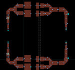
First i made my design in line an schematic antwort was like momentum
But because i want smaller circuite i change it and add some bend and my schematic aswer 20 dB more than momentum design
Is it normal?
Of course, 20dB difference is not "normal", so you need to look for mistakes.
It looks like your dimensions do not match, there is some overlap (pin position conflict) in the top left feed.
And several nodes show that nothing is connected.
What did you compare, the schematic with microstrip models to the Momentum result of the same layout?
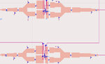
One possible mistake with Momentum (not related to bend) is the port width, at positions where the device terminal width is very different from the edge of the line where the port is placed.
Of course, 20dB difference is not "normal", so you need to look for mistakes.
It looks like your dimensions do not match, there is some overlap (pin position conflict) in the top left feed.
And several nodes show that nothing is connected.
What did you compare, the schematic with microstrip models to the Momentum result of the same layout?
One possible mistake with Momentum (not related to bend) is the port width, at positions where the device terminal width is very different from the edge of the line where the port is placed.
thank you for ur attention
i correct it and nothing happen
i separate my design
first i get input layout and put its diagram there and my answer decrease more than 20 dB (rest of it was from my schematic)
then i get output and it decrease 10 dB (rest of it was from my schematic)
then i try get lay out up to bend and it has different from schematic and ..... i think i should try to tune it in momentum but it needs too much time
i will try " Control the port size and location" but if nothing happen can i upload my design here and you checked it
another question is in this
i cannt optimize most of my design
It seems that you have more mistakes then. Is your co-simulation schematic correct where Momentum and circuit models are connected?
Have you checked tutorials on co-simulation?
Maybe you start with a very simple co-simulation, just two lines with a series resistor between the lines. That is enough to understand the co-simulatoon workflow.
One more possible issue: if you are doing co-simulation with a non-linear model, and your DC path is through the Momentum model, then your Momentum frequency range MUST go down to DC!
This site uses cookies to help personalise content, tailor your experience and to keep you logged in if you register.
By continuing to use this site, you are consenting to our use of cookies.