Continue to Site

Welcome to EDAboard.com

Welcome to our site! EDAboard.com is an international Electronics Discussion Forum focused on EDA software, circuits, schematics, books, theory, papers, asic, pld, 8051, DSP, Network, RF, Analog Design, PCB, Service Manuals... and a whole lot more! To participate you need to register. Registration is free. Click here to register now.

Basic: How do I wire microswitches to a 14 seg display?

Status
Not open for further replies.

cargeek

Newbie level 3
Joined
Jul 27, 2009
Messages
4
Helped
0
Reputation
0
Reaction score
0
Trophy points
1,281
Activity points
1,307
how to wire micro switches in series

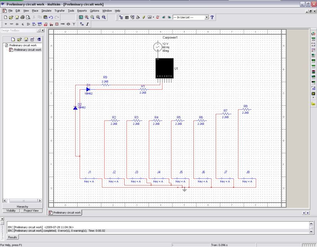
I want to mount microswitches to the shifter in my car, and wire those switches to a 14-seg display on my dashboard to display the numbers 1-6 and the characters R and N. I am an electronics noob and have tried researching segmented displays and simple circuit designs and sort of get the basics (like, I get parts, the assembly), but the major hurdle for me is understanding how to integrate the parts into a circuit and why. I understand I'll need a 14-seg display, a BCD, microswitches, breadboard, resistors, and wiring, but I know I'm either missing or overthinking what I'm doing with the circuit. This is going to be wired into my 2003 Audi. Could you all help a newbie out with recommended parts, part numbers, or even some circuit plans? I've got Electronics Workbench v9.0, if that helps...thanks a lot everyone :D
 

microswitches

If you can arrange the switches so that one, and only one, switch is closed for each gear ratio then you can do it like this.


Resistor in series with each segment, exact value dependent on the brightness you want. Maybe the smaller segments need a slightly higher resistor value than the others to get the brightness the same?

Diodes to each switch contact, one per segment that you want that switch to light up

This could be built nicely on a large piece of stripboard.

A common-cathode display could be used with the diode direction reversed and the power connections the other way around.

This seems like a good way for a beginner to build it. It could be made physically smaller with a 40 pin microcontroller instead of about three dozen diodes.

Don't forget a suitable fuse close to the source of the electrical power for the display. It should be at the source end of the power cable so it will blow if something happens to the cable. (I assume this is a modern negative earth car so you put the fuse in the positive lead)


Usual disclaimers apply, do not attempt any modifications to your vehicle unless you are competent to do so safely.
 

how to wire in a micro switches

Thanks! :) Here is what I have gotten together so far on Multisim...it seems right, but the "1" will not appear; I used 2200ohm resistors but just randomly picked diodes (which diode is the one to use?) Is anything obviously wrong with it?:

prelimset-up2.jpg


I am using the diagram from throwaway and this one for guidance (though I'm adapting it for my 14/15-seg display):

**broken link removed**

I do like the idea of the micro-controller you mentioned throwaway (I'm trying to keep this as compact as possible)...could you elaborate more? (again, sorry I'm a noob) Anyway, thanks for the help, I plan to get this together ASAP and post pics
 

Status
Not open for further replies.

Similar threads

Part and Inventory Search

Welcome to EDABoard.com

Sponsor

Back
Top