Continue to Site

Welcome to EDAboard.com

Welcome to our site! EDAboard.com is an international Electronics Discussion Forum focused on EDA software, circuits, schematics, books, theory, papers, asic, pld, 8051, DSP, Network, RF, Analog Design, PCB, Service Manuals... and a whole lot more! To participate you need to register. Registration is free. Click here to register now.

Analog Electronic Exercises

Status
Not open for further replies.

uniluigi

Newbie level 4
Joined
May 28, 2012
Messages
6
Helped
0
Reputation
0
Reaction score
0
Trophy points
1,281
Activity points
1,318
Hi, I'm new here and I'm studying analog electronic from Sedra Smith ( 6th ed ). In this book exercises are without solution and I can't find them ( cos they are reserved for teachers only ).
I've read some threads in this forum but link doesn't work anymore maybe because they are old right now.
Does someone have any exercises? I need them about op-amp, bjt, fet, diodes and feedback.
Thank! :roll:
 

uniluigi,

Does someone have any exercises?

Sure, I have plenty of exercises. If you want answers, you have to work them out yourself with help from this forum.

Ratch
 

uniluigi,


Sure, I have plenty of exercises. If you want answers, you have to work them out yourself with help from this forum.

Ratch

Yeah I will maybe for more difficult ones! Thanks!
 

If you do exercises from the book, people here can check your answers for you.
 

I don't know if I can post here one exercises ( maybe only for my first time )

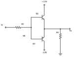
This is the schematic:
**broken link removed**

For the circuit find Vb, Ve for Vi = 0V, -3V, 5V. The BJT have \[\beta\] = 100.

First of all both Q1 and Q2 can't be on in the same time.
I've done: for Vi = 0V. If Q1 is off and Q2 is on, current pass through 1k\[\Omega\] resistor to the emitter of Q2. Then it flow out the base to the 10k\[\Omega\] resistor in Vin.

So Vb is 0.07V and Ve is about 0.707V

For Vi = -3V it's almost the same except for the final result.
Vb is 0.25V and Ve is 2.5V

For Vi = 5V, Vb is negative so cos current have to flow into the base, Q2 is off and Q1 is on. Thus current flow from 10k\[\Omega\] resistor to the base of Q1 , then into the emitter to the 1k\[\Omega\] resistor.
Vb is 4.6V and Ve is 3.9V

I don't know if it's correct! :-|
 

I can't see the attachment.

Can you see it now?
schemeit-project.png
 

I see the pictures now. Sorry but the answers are all wrong. Here are some ideas to help:
First of all both Q1 and Q2 can't be on in the same time.
That is true but remember Q1 and Q2 can both be off at the same time.

For Vi = -3V......
Vb is 0.25V and Ve is 2.5V
The difference between Vb and Ve can not be more than about 0.7V. If one transistor is on, there is 0.7V difference between Vb and Ve. When there is less than 0.7V between Vb and Ve then both transistors are off.
For Vi = 5V........
Vb is 4.6V and Ve is 3.9V
Ve can not be higher than +2.5V or lower than -2.5V.
 

I've corrected the exercises:
1) Vi = 0 then Q1 and Q2 are off so Ve = 0, Vb = 0;
2) Vi = 3V ( it's 3V, not -3, my mistake ) then Q1 is on and Q2 is off and Ve= 2.09, Vb= 2.79 ( then Vbe = 0.7V );
3) Vi = -5V. I can't do it. I think Q2 is on and Q1 is off but I'm can't explain why. In this way Ve will be lower than -2.5V.

Help :/
 

Hi

The answers for 1 and 2 are correct.
In question 3, the bottom transistor (Q2) is saturated. When the voltage between the collector and emitter of a transistor is very low, then the current gain also becomes low. Typically the current gain is only about 10 when the voltage is about 100mV. As the voltage gets smaller, the current gain also gets smaller. Eventually the current gain becomes less than 1, and the collector current is less than the base current.

For this question, I think the voltages and currents will be like in the picture below, with about 100mV between the collector and emitter. Different transistors are different though, so it may be 50mV with one transistor and 200mV with another.


Really thanks! There are a lot of thing to learn like these.
My question is: is there a fast way to know which trasistor is on with that configuration?
 

If the input voltage is higher than +0.7V, then Q1 is on.
If the input voltage is lower than -0.7V, then Q2 is on.
 
Status
Not open for further replies.

Similar threads

Part and Inventory Search

Welcome to EDABoard.com

Sponsor

Back
Top