Continue to Site

Welcome to EDAboard.com

Welcome to our site! EDAboard.com is an international Electronics Discussion Forum focused on EDA software, circuits, schematics, books, theory, papers, asic, pld, 8051, DSP, Network, RF, Analog Design, PCB, Service Manuals... and a whole lot more! To participate you need to register. Registration is free. Click here to register now.

amplify DAC output to 12V

Status
Not open for further replies.

Fidias

Newbie level 3
Joined
May 28, 2014
Messages
3
Helped
0
Reputation
0
Reaction score
0
Trophy points
1
Activity points
23
Hello,

I am working on a school project and I need to drive a 12V DC motor/fan using a DAC so that I can control its rotation speed. The DAC that I am using is the AD5662 and I use it to output 0-3.3V. At first I was using PWM and a transistor and it was working fine but now my professor wants me to use the DAC instead of the PWM. The wiring was like this:
8170383000_1401279093.png


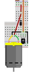
The orange cable is the PWM output coming from the Raspberry Pi. I tried to replace the PWM output cable with the DAC output cable but then the motor starts for a few seconds and then stops unexpectedly. Then I tried amplifying the output using an op amp (TL071CP) unfortunately with no success. I tried both non-inverting and inverting with no success. So my question is how can I amplify the DAC output in order to drive the motor and why the op amp I am using does not work (e.g. do I need a rail-to rail one)? Also I have connected the VCC- pin of the op amp to the ground is that fine?

Sorry if I said something "stupid", but I am kind of a newbie on this stuff :).
 

Yes, the motor stops due to insufficient torque which is proportional to supply voltage to motor. And the way PWM works is PWM from microcontroller works on same supply of microcontroller i.e. 0 to 3V suppose. This is amplified with MOSFET driver through actual motor supply. When using DAC, make sure you have cnnected the motor between DAC output and ground and if DAC output is insufficient, use MOSFET or transistors or the high gain amplifier.
Plz do tell which motor are you using to make specific solution for running motor.

Hope that helps.
 

I have added a capacitor (1uF) in exactly the same place as the diode and I can now drive the motor using the DAC output directly. However, the resulting rotation speed is strange. For values higher than 16000 (is a 16 bit DAC so it has 65535 values) the motor seems to work at full speed, for values between 15000 and 16000 the speed changes and for values lower than 15000 the motor is off. The transistor that I use is the PN2222. Any idea why this is happening?

I am afraid I do not have more details about the motor as the professor gave it to me without a datasheet or anything but it looks exactly like this one
**broken link removed**
 
Last edited:

This behavior of motor mostly due to sudden change in current i.e. for a very small change in motor supply voltage through DAC (i.e. 15000 to 16000), there is huge change in current supplied to motor which is not the case in PWM as seen from your experiments. This may be due to non-linearity in DAC output or amplifier after it. If you are using transistor as output stage check whether it is operating in its linear region, if not change it. Remember that, in case of PWM transistor acts as switch which will provide average voltage and current and its linearity does not matter but when DAC output is given, transistor operates in its active region rather than switch, this is where it can be non-linear. SO, i suggest replace transistor with high gain and high output current op-amp if motor is small or else change the transistor which operates in entire region of DAC output.

If possible can you make a block diagram at least (schematic will be good) and share it. It will be more clear and solution will be obvious, if design is here.
Also, motor info is required too, plz consult your professor and find out if its 3-phase permanent magnet BLDC motor, or self start dc motor etc.

Hope that helps.
 

The motor draws its maximum current when it starts running and when it is stalled. Simply measure its resistance then use Ohm's Law to calculate its maximum current. It is probably destroying your low current little PN2222 transistor.

Please post a detailed schematic instead of your wiring layout.
 

Status
Not open for further replies.

Part and Inventory Search

Welcome to EDABoard.com

Sponsor

Back
Top