Continue to Site

Welcome to EDAboard.com

Welcome to our site! EDAboard.com is an international Electronics Discussion Forum focused on EDA software, circuits, schematics, books, theory, papers, asic, pld, 8051, DSP, Network, RF, Analog Design, PCB, Service Manuals... and a whole lot more! To participate you need to register. Registration is free. Click here to register now.

555 ir2110 mosfet switching

Status
Not open for further replies.

varunme

Advanced Member level 3
Joined
Aug 10, 2011
Messages
741
Helped
17
Reputation
36
Reaction score
17
Trophy points
1,318
Activity points
5,764
Dear all,
I am making a variable frequency DC source, for that, I am using 555
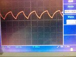
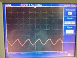
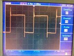
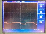
The frequency generated is fed to ir2110, which drives IGBT, but I am having issues in switching, I am attaching the schematic and waveforms generated by 555, ir2110, and IGBT here.

high-side-mosfet-driver.png

This is the waveform generated by 555,
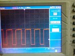
DSO (9)(7).jpgFrom ir2110DSO.jpgFrom IGBTDSO (7).jpg

When frequency is increased

555
DSO (8)(7).jpgFrom IGBT DSO (11)7).jpg


What can be the issue and how can it be corrected?
--- Updated ---

Is it, bootstrap circuit making problem? should I lower the capacitance?
 
Last edited:

Hi,

"Variable frequency" and "DC" contradicts somehow...

Circuit problem:
I think IR21xx circuits are the most discussed problems here.
Indeed there are just a couple of mistakes. Made very often. But instead of looking into datasheets, application notes or one of the many discussions...one start a new discussion...

As with in at least 20% of the discussions:
* without load and without low side Mosfet the bootstrap capacitor can't charge properly, thus tge high side driver can't work properly

Klaus
 
So I need to add low side circuit too?
 

Hi,

As already said: " ... or add a load..."

I recommend to read application notes. They explain everything in detail. More detailed than we can. With schematics, scope views, calculations...
A forum is meant that others can gain from previous discussions.


Klaus
 
The high side bootstrap driver can only work if VS node is pulled to ground in output off state. Either by the load or the low side switch of a full push-pull circuit.
 
the circuit shown won't work without an isolated 12 - 15V supply for the high side part of the circuit ...
 
  • Like
Reactions: varunme

    varunme

    Points: 2
    Helpful Answer Positive Rating
Without seeing what you are driving with the fet its difficult to help you.
Maybe if you put in a low side switch (to achieve bootstrap cap refresh) then it will interfere with what you are driving, but we do not know, because you do not show it.
What you could do, is just remove the 1n4148 and put a fully isolated power supply across the 33uf...then your circuit will work as it is.
...oops, just seen Easy Peasy had just said that..sorry
 
  • Like
Reactions: varunme

    varunme

    Points: 2
    Helpful Answer Positive Rating
FvM has the correct answer.

With an N-ch MOSFET, the gate drive to turn on MOSFET must go at least 10v above its source.

The 2110 uses a bootstrap upper driver capacitor supply. The 'ground' side of the upper stage is the Vs pin. It rises up when a lower MOSFET is turned off. C1 capacitor must be recharged periodically to re-establish the voltage across the bootstrap capacitor. This is normally done in a push-pull stacked MOSFET pair when the bottom MOSFET is turned on. The diode passes the capacitor recharge current.

The driver must work with a continously chopping output push-pull configuration otherwise the upper driver power supply will be depleted.

You could provide a separate isolated 12 to 15v supply across C1 to provide continuous DC supply to upper driver of 2110. It must be isolated so it can float up and down with your external MOSFET source voltage.
 
  • Like
Reactions: varunme

    varunme

    Points: 2
    Helpful Answer Positive Rating
Thanks for all help, I will try all and update here
--- Updated ---

FvM has the correct answer.

With an N-ch MOSFET, the gate drive to turn on MOSFET must go at least 10v above its source.

The 2110 uses a bootstrap upper driver capacitor supply. The 'ground' side of the upper stage is the Vs pin. It rises up when a lower MOSFET is turned off. C1 capacitor must be recharged periodically to re-establish the voltage across the bootstrap capacitor. This is normally done in a push-pull stacked MOSFET pair when the bottom MOSFET is turned on. The diode passes the capacitor recharge current.

The driver must work with a continously chopping output push-pull configuration otherwise the upper driver power supply will be depleted.

You could provide a separate isolated 12 to 15v supply across C1 to provide continuous DC supply to upper driver of 2110. It must be isolated so it can float up and down with your external MOSFET source voltage.
I am using IGBT here instead of MOSFET
 
Last edited:

I am using IGBT here instead of MOSFET
Yes I noticed, makes no big difference, the part behaves quite similar. We still don't know which load is connected in your measurement, or is it open circuit?
 
  • Like
Reactions: varunme

    varunme

    Points: 2
    Helpful Answer Positive Rating
Yes, I noticed, makes no big difference, the part behaves quite similar. We still don't know which load is connected in your measurement, or is it open circuit?
I tested as Open circuit, as directed by all, I will connect DC motor load with diode and update here.
The final circuit is intended for electrochemical use
 

Hi,

a motor is an inductive load.
Don´t forget to add a free wheeling diode or an overvoltage proctetion at the MOSFET.

Klaus
 
Status
Not open for further replies.

Similar threads

Part and Inventory Search

Welcome to EDABoard.com

Sponsor

Back
Top