Continue to Site

Welcome to EDAboard.com

Welcome to our site! EDAboard.com is an international Electronics Discussion Forum focused on EDA software, circuits, schematics, books, theory, papers, asic, pld, 8051, DSP, Network, RF, Analog Design, PCB, Service Manuals... and a whole lot more! To participate you need to register. Registration is free. Click here to register now.

12V battery recharger circuit

Status
Not open for further replies.
Using an Arduino to charge a battery is overkill! I was thinking of a $1 PIC.

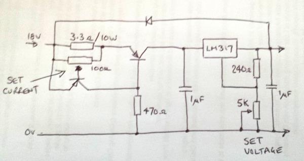
You have spotted the problem with using the transistor as the current regulator, what it doesn't let through is converted to heat and "the charge current gradually decreases" isn't the optimal way to charge the battery. You will get similar results by just using a series resistor! Although it works, the charge current slows dies away to nothing so the time taken to reach full charge is much longer than if you 'force feed' it.

Ideally, you want the voltage to adjust so it is *just* high enough to make a fixed current flow into the battery and at the point where the battery voltage levels off you switch to constant voltage and let the battery draw what it wants until full charged.

Brian.
 

Brian what do you think of this version of my battery charger circuit:

BatteryCharger4.jpg

This is the control circuit for those digitally selected transistors:

BatteryCharger3.jpg
I just realised that I am missing a 36k resistor on the base of Q15.

Notice the LEDs labelled LM317_4_5V, LM317_9V and LM317_13_5V.
 
Last edited:

For some reason I can't view the images at the moment, I'll try again tomorrow when the internet traffic is quieter.

Brian.
 

For some reason I can't view the images at the moment, I'll try again tomorrow when the internet traffic is quieter.

Brian.

In multisim, I hooked the control circuit up to the LM317 circuit however it appears that there is too much leakage current from my control circuit that is turning on the transistors inappropriately.

The control circuit work perfectly with the LED only however. But they are a lot more forgiving of leakage currents.

It may work better with TTL gate ICs (74H...)
 

I'm not sure how the contol circuit hooks up to the regulator transistors. However, using PNP transistors isn't a good idea in this application because you need to supply enough base current to saturate them or turn them off completely and the current return is through the emitter pin which has a varying voltage on it. If you use NPN types the emitters can be grounded so you have a safe current sink. All you need to do is give them enough base current and they effectively ground the bottom of the voltage setting resistors.

Things to watch out for:
1. if all transistors are turned off, the regulator will no longer work, unless you are certain that at least one transistor will be 'on', I suggest you add a fixed resistor between ADJ and ground to set a maximim output voltage.
2. To get a reliable switching threshold where the LED lights up, the comparator reference voltage has to be constant. At the moment it is proportional to the input voltage, decided by R6 and R7. If the input is not regulated, I would add something, maybe a Zener diode to stabilize the reference.

You can switch more than one transistor on at a time so your voltage combinations are 2^number of transistors. In other words you can already select 8 different voltages from the three transistors you have.

Brian.
 

I change those transistor logic gates to logic ICs and it works well in multisim.

ControlCircuit.jpg

The bit with the LM393s is one of those logic ladders where each 'unit' outputs a transition from HIGH -> LOW when the reference voltage is exceeded (as the battery charges up).

The BC558s simply reverse the logic with output transitions from LOW to HIGH.

Then there are voltage dividers on those outputs to take the voltage down to 5V compatible with the logic ICs.

When the battery voltage is 0 - 4.4V the first unit of the logic ladder turns on.
When the battery voltage is 4.5 - 8.9V the first and second units of the logic ladder turn on.
When the battery voltage is over 9V the first, second and third units of the logic ladder turn on.

So the purpose of the logic ICs is to change the above scenario to the following one:

When the battery voltage is 0 - 4.4V the first unit of the logic ladder turns on.
When the battery voltage is 4.5 - 8.9V the second unit of the logic ladder turns on.
When the battery voltage is over 9V the third unit of the logic ladder turns on.

I suppose what I have created is a simple ADC.

Those logic ladder units are then connected to the bases of the transistors in my LM317 circuit - digitally selected voltage outputs.

I am now trying to figure out how to implement the change over to constant current thing. This works fairly well but I will do a bit more research to see if there are any better solutions.

LM317circuit.jpg
 
Last edited:

I'm not sure I would call it a 'simple' ADC but yes it is one. I think you are overcomplicating it to be honest and if you really wanted to use an ADC it would only be slightly more complicated to use a window comparator system so you could use all the possible voltage selection combinations. In other words all the possible binary values to turn the transistors on.

Incidentally, the output of the LM393 is open-collector so you can pull it up to 5V through a single resistor, even when it is powered from 18V, there is no need to do the voltage scaling and you can reverse the logic if necessary by swapping the comparator inputs over.

You could consider swapping the current limit and voltage regulation stages over so current limiting comes first, that makes it easier to follow the battery voltage rise as it charges and the current can never exceed the limit anyway.

Brian.
 

window comparator system so you could use all the possible voltage selection combinations. In other words all the possible binary values to turn the transistors on.
Brian.
No idea what a window comparator system is.
With the LM317 digital voltage selection circuit you can only select as many transistor/resistor/voltage combinations that you have inserted.
So I don't understand why the ability to trigger on an almost continuous voltage range is of any benefit.

Incidentally, the output of the LM393 is open-collector so you can pull it up to 5V through a single resistor, even when it is powered from 18V,
Brian.
Oh! I did not realise you could do that.

You mean pull all the LM393 outputs up to 5V off one voltage divider rather than use 3 voltage dividers on each output - fewer components.

there is no need to do the voltage scaling and you can reverse the logic if necessary by swapping the comparator inputs over.
Brian.
Of course! Forgot about that.

You could consider swapping the current limit and voltage regulation stages over so current limiting comes first, that makes it easier to follow the battery voltage rise as it charges and the current can never exceed the limit anyway.
Brian.
Oh OK. So I would be dropping 2V or so off the 18V input rather than off the LM317s output. That would be much better. Thanks.

- - - Updated - - -

Actually Brian I can't do without those BC558 on the LM393.

Because the LM393s are current sink devices, so their 'naked' outputs wont work with the logic gates. I should have said they were their to reverse the current flow rather than reverse the logic output.
 
Last edited:

A window comparator is very similar to a normal comparator except it has two thresholds. It turns on as one is passed and off again when the other is passed. It would allow you to overlap the voltages, for example comparator 1 might turn on at 1V and off again at 3V, comparator 2 turn on at 2V and off at 4V and comparator 3 turn on at 3V and off at 5V. From the three outputs and some logic decoding you can see what the voltage is in 1V steps instead of just whether it is above certain levels.

The LM393 output is not committed to any voltage, it can only pull the pin low and relies on the output resistor to lift it to 'high' level. That allows you to connect the pull-up resistor to any voltage you like within range of the IC. As you already have a supply for the logic gates, use that as the top of each pull-up resistor and the levels will automatically match the ones needed by the gates. You can experiment by removing all the logic and transistors, connecting the outputs of the LM393 directly to the voltage setting resistors on the LM317, in other words using it's internal output transistors instead of the three switch transistors, it should work exactly the same but with far fewer components.

Brian.
 

A window comparator is very similar to a normal comparator except it has two thresholds. It turns on as one is passed and off again when the other is passed. It would allow you to overlap the voltages, for example comparator 1 might turn on at 1V and off again at 3V, comparator 2 turn on at 2V and off at 4V and comparator 3 turn on at 3V and off at 5V.
Brian.
I am not sure that understand how that is advantageous.

The LM393 output is not committed to any voltage, it can only pull the pin low and relies on the output resistor to lift it to 'high' level. That allows you to connect the pull-up resistor to any voltage you like within range of the IC. As you already have a supply for the logic gates, use that as the top of each pull-up resistor and the levels will automatically match the ones needed by the gates. You can experiment by removing all the logic and transistors, connecting the outputs of the LM393 directly to the voltage setting resistors on the LM317, in other words using it's internal output transistors instead of the three switch transistors, it should work exactly the same but with far fewer components.
Brian.
Would you be able to do a circuit diagram of what you mean?
Not the whole circuit obviously - just the relevant transistors and resistors.
 

Sorry for the delay - I'm in the process of moving home so sometimes I can't get to a computer.

I've attached the internal circuit of the LM339 and circled the part I mean. You will note the output transistor has it's emitter connected to ground and the collector is not connected to anything inside the IC, it just comes out on a pin. Look back at the schematic where the three transistors are used to control the LM317 output voltage and you will see it is possible to use the circled transistor as a replacement for one of the discrete transistors. In other words you could remove all the other parts you use to scale the voltage and the logic gates and just connect the LM339 output directly to the voltage programming resistor instead of the transistor.


Alternatively, you could try this simple circuit. Sorry for the poor sketch, it is untested but should work:


It puts a simple current limiting stage before the voltage regulator as I suggested earlier.

Brian.
 

I just came up with this pre-LM317 current limiting circuit Brian.

CurrentLimiting.jpg

What is your opinion of this one?

It seems to work in multisim, with the transistor hard on when the battery voltage is below 11.5V and hard off when the battery reaches that voltage. It seems to solve your constructive criticism about the power being wasted in a partially turned on transistor in the very first version of my circuit.

But on second thoughts I am wasting power in the 100R resistor now instead of the transistor.
 
Last edited:

Correct. It isn't a current limiter at all, not in the usual sense anyway. It is a voltage operated switch, the transistor is turned on when the battery voltage is below 11.6V and there is no current limit. When it reaches 11.6V, the comparator turns the transistor off and the charge current is limited only by the 100R resistor. So yes, it will work but consider what happens if you connect a shorted battery or one that tries to continuously draw too much charging current because it never reaches 11.6V across it's terminals.

Brian.
 

Brian I have looked into that window comparator idea you suggested but the resulting circuit did not seem to be any simpler than the way I implemented with the straight voltage level comparator system + logic circuit.

You can't have the window comparator voltage ranges overlapping because then you would end up with two of the LM327 digital select transistors turning on.

But if the voltage ranges do not overlap then there are inevitably small voltage gaps between the window comparator voltage ranges. So then I had to use logic circuits to deal with those anyway.

So I reverted to my original design and added an additional voltage trigger level an LM317 voltage level.

So a few millivolts will trigger LM317 - 2.5V, then 2.55V will trigger LM317 - 5V, then 5.1V triggers LM317 - 7.5V, then 8.6V triggers LM317 - 13V and then 12V triggers LM317 12.3V for trickle charging.

I figured out this pre-LM317 short circuit protection:

ShortCircuit.jpg

In multisim, it seems to work with only a 0.8V drop across the BD139.

- - - Updated - - -

Brian I have looked into that window comparator idea you suggested but the resulting circuit did not seem to be any simpler than the way I implemented with the straight voltage level comparator system + logic circuit.

You can't have the window comparator voltage ranges overlapping because then you would end up with two of the LM327 digital select transistors turning on.

But if the voltage ranges do not overlap then there are inevitably small voltage gaps between the window comparator voltage ranges. So then I had to use logic circuits to deal with those anyway.

So I reverted to my original design and added an additional voltage trigger level an LM317 voltage level.

So a few millivolts will trigger LM317 - 2.5V, then 4.5V will trigger LM317 - 5V, then 7V triggers LM317 - 7.5V, then 9.5V triggers LM317 - 13V and then 12V triggers LM317 12.3V for trickle charging.

I figured out this pre-LM317 short circuit protection:

ShortCircuit.jpg

In multisim, it seems to work with only a 0.8 - 1.0V drop across the BD139.
 
Last edited:

I'm still not sure how the current limiting is supposed to work when nothing monitors what the current actually is. Are the resistor values R60 & R61 correct, it seems to be producing a very small voltage for the comparator. I would also connect the cathode of D1 to 18V, it is there so that if the 18V supply is turned of while a charged battery is still connected the voltage across the whole circuit is limited to 0.7V, without it the transistor Q11 may have full battery voltage across it in reverse.

Brian.

Because the if there is no battery between the 5.6R resistor and GND then the voltage at the monitoring point will be 0V. That would be below the 2 (or so) mV of the comparator reference voltage, whose output would therefore go to 5V and thus turn off the BC558 which, in turn, would turn off the BD139.

I suppose it is possible that a bad battery might have a voltage of 2mV and not trigger the circuit breaker, but it is unlikely.
 

There is no 5.6 Ohm resistor in the schematic you posted! I suspect you took a snapshot of only part of the schematic, the measuring input of the comparator isn't shown.

It may work but I would urge caution when using thresholds as low as 2mV because a voltage as small as that is quite easy to produce from the resistance of the wiring alone, especially when relatively high currents are invoved. It is only 2mA in 1 Ohm or looking at it the other way, 1 Amp in 2 milliOhms. You may well find it oscillates in real life as the current is switched on and off and that in turn would make the comparator change state and start the curent again cyclically.

Brian.

Oh. Generally speaking, what would you suggest is a safe minimum value to use with comparators then
 

There isn't technically a safe or unsafe value but when you use such small differences as 2mV you will find other voltage drops in the circuit and even supply ripple and noise start to look in comparison. For example, if the bottom resistor in the comparator reference had as little as 0.002 Ohms in series with it and 1A flowed along the ground wire, it would be enough to fool the comparator into changing state. If you can, try to make the difference in 'on' and 'off' levels as big as possible. This is why some of the other circuits you showed had an op-amp connected across the sense resistor, it was to amplify the voltage dropped across it so the resistor could be lower value and so the comparator saw a bigger voltage difference.

As for what I would suggest is a safe level would depend on the construction you were using and how 'clean' the 18V rail is but as a rule of thumb I wouldn't go below about 100mV.

Brian.
I think it is safe to assume that it is just not practical to implement a transistor based 'fuse'. At least not in the way I have been trying to do it. Far easy to just stick in an actual fuse - 1A or so.

The current limiting is done by the selectable voltage output and the 5.6R resistor. I have done a fair bit of testing and it never seems to go above 600mA. The current drops to a few tens if mA as the battery voltage approaches the next trigger level and then goes back up to a few hundred mA when the next voltage level is triggered.

Short of being a perfect re-charger circuit, are you of the view that it will do an adequate job for a 7Ah gel cell?
 

Status
Not open for further replies.

Part and Inventory Search

Welcome to EDABoard.com

Sponsor

Back
Top