OradFarez
Member level 1
Hello. I usually do digital design but I need to make a MOSFET circuit that enables a power supply to drive a load or be removed. This is so that I can have one supply active only when another one is already on.
I have a 2.8V supply (VIOHI) and a 3.3V supply (3.3V_RAW) as shown in the picture below. The load is attached to the 3.3V net:
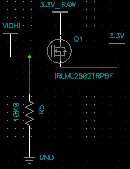
I have seen N-Channel MOSFETs used to sink a power source to ground and the positive end of the load is always connected but I want the opposite. Will this circuit work? Is there a better way?
Thank you!
I have a 2.8V supply (VIOHI) and a 3.3V supply (3.3V_RAW) as shown in the picture below. The load is attached to the 3.3V net:
I have seen N-Channel MOSFETs used to sink a power source to ground and the positive end of the load is always connected but I want the opposite. Will this circuit work? Is there a better way?
Thank you!