jack_yls
Newbie level 6
Currently, I have some design problem.
Analog design, power supply. 1 of the important component in power supply is capacitor. So, as we all know, capacitors have at least 2 basic functions, store charge and filtering the noise (particular frequency). Capacitors have different capacitance, time response and impedance.
For bypass capacitor, I use “Try and Error” method and basic calculation of impendence (capacitor). I have found some alternative capacitor for replacement (for cost down/ Value Added). However, there are some concepts I’m not sure.
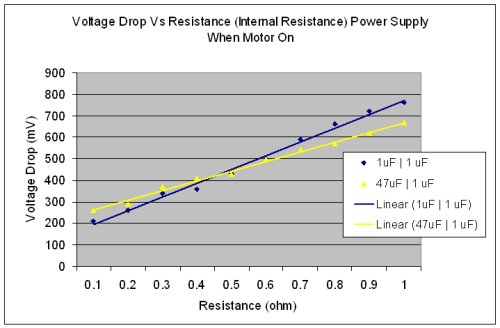
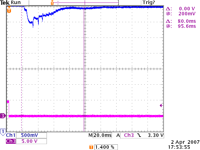
FYI. The graph below is the voltage drop when the circuit ‘ON’. When the circuit ON, the voltage of the VCC circuit drop a little bit; then, capacitor discharge and provide the charge (current) to the circuit and the voltage will become stable after certain time.
The questions here are, if I use bigger value of (capacitance), the voltage drop should be better (not so much voltage drop), as the big value of capacitor can store more charge? How about the time response of different capacitor? Ecap capacitor is response faster than ceramic capacitor?
Analog design, power supply. 1 of the important component in power supply is capacitor. So, as we all know, capacitors have at least 2 basic functions, store charge and filtering the noise (particular frequency). Capacitors have different capacitance, time response and impedance.
For bypass capacitor, I use “Try and Error” method and basic calculation of impendence (capacitor). I have found some alternative capacitor for replacement (for cost down/ Value Added). However, there are some concepts I’m not sure.
FYI. The graph below is the voltage drop when the circuit ‘ON’. When the circuit ON, the voltage of the VCC circuit drop a little bit; then, capacitor discharge and provide the charge (current) to the circuit and the voltage will become stable after certain time.
The questions here are, if I use bigger value of (capacitance), the voltage drop should be better (not so much voltage drop), as the big value of capacitor can store more charge? How about the time response of different capacitor? Ecap capacitor is response faster than ceramic capacitor?