Welcome to our site! EDAboard.com is an international Electronics Discussion Forum focused on EDA software, circuits, schematics, books, theory, papers, asic, pld, 8051, DSP, Network, RF, Analog Design, PCB, Service Manuals... and a whole lot more! To participate you need to register. Registration is free. Click here to register now.
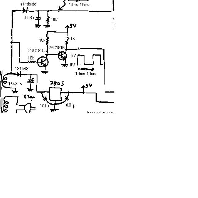
Can I use a 555 timer in this schematic to increase the pulse rate vs. using the 2 switching transistors. With the transistor configuration, I get flicker on a scope. If not, how can I rearrainge the transistors to double the speed.
This circuit appears to be a zero-crossing detector. The edges of the square wave correspond to the zero crossing of the incoming AC power line frequency.
While you could easily produce a 555 timer circuit that had an output at twice this frequency, it would no longer be correlated or synced to the power line frequency.
What exactly are you trying to do? Is tracking the power line important to you? Since you mention an o-scope, please be aware that if you are attempting the usual ultra low cost "curve tracer" then flicker is normal.
You are using 50 Hz as input so the output is also same. Double the input frequency by full-wave rectification of input to zero crossing detector, the output of the ZCD will also be 100 Hz.
I do not see how full wave rectification helps. The transistor's base is fed with raw AC without any pre-rectification. The transistor saturates on the positive half cycle and then cuts-off for the negative half cycle. This gives a 50-50 duty cycle. If you full-wave rectify, (which would require a different transformer with a center tap), you will get the transistor saturated most of the time. The output would be a series of very narrow pulses at 100HZ, but the duty cycle would be probably 90-10, or maybe even 95-5.
This site uses cookies to help personalise content, tailor your experience and to keep you logged in if you register.
By continuing to use this site, you are consenting to our use of cookies.