Continue to Site

Welcome to EDAboard.com

Welcome to our site! EDAboard.com is an international Electronics Discussion Forum focused on EDA software, circuits, schematics, books, theory, papers, asic, pld, 8051, DSP, Network, RF, Analog Design, PCB, Service Manuals... and a whole lot more! To participate you need to register. Registration is free. Click here to register now.

Normal Keypad Interface to PC Via PS2

Status
Not open for further replies.

Help

Advanced Member level 2
Joined
Feb 15, 2005
Messages
617
Helped
7
Reputation
14
Reaction score
3
Trophy points
1,298
Activity points
7,065
keypad interface for pc

Hi,

I am doing testing for 4x4 Keypad interface to PC via PS2. Doing a small KeyBoard. What can i do?

I found one good article but that is interfacing to PC via RS232.

Thank You.
 

interfacing a keypad in the pc

Your PDF describes the way a PC keyboard can be connected to a microcontroller ..
In your case you need to do the opposite: simulate keyboard (keypad) ..

Select a microcontroller and program it to read 4x4 keypad ..
Then, take a look at the attached pictures ..
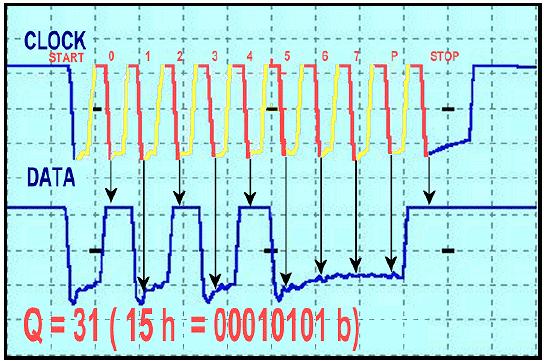
One is showing timing on CLK and DATA lines, the other shows keyboard codes and briefly describes sequence of bytes that your microcontroller has to send to a PC through the PS2 port ..

Also, see info on initialization which is the communication between a computer and keyboard when it boots-up, so computer will accept your keypad:
**broken link removed**

Regards,
IanP
 

    Help

    Points: 2
    Helpful Answer Positive Rating
ps2 f2 ab read id keyboard

Please take a look at :

:arrow:
 

    Help

    Points: 2
    Helpful Answer Positive Rating
vcc 4x4 keypad

Hi,

I have to prepare two thing in my code:
1 – Keypad code
2 – Protocol: Start Bit, 8-data bits, one Parity bit and Stop bit (11-bits). The format follows according the fig1.
Ex:
1- Pressing Q
2- uC send 0x15h to PC (pressing)
3- uC send 2bytes F0 and 15 to PC (release)
86_1170046330.jpg

Am i right?
What is Parity bit? When we have to set 1/0?

IanP said:
Also, see info on initialization which is the communication between a computer and keyboard when it boots-up, so computer will accept your keypad. IanP

I am not sure on this part? Please can you explain to me.
You mean the PC must initializa the Keypad when boots-up(On PC) that time then the Keypad can use?

Keyboard: AA Self-test passed ;Keyboard controller init
Host: ED Set/Reset Status Indicators
Keyboard: FA Acknowledge
Host: 00 Turn off all LEDs
...
How to send the commands to pc? Without sending this commands from initial then my keypad wouldn't work?

Thank You.
 

ps/2 odd parity

The parity bit is set if there is an even number of 1's in the data bits and reset (0) if there is an odd number of 1's in the data bits ..
The number of 1's in the data bits plus the parity bit always add up to an odd number (odd parity.) ..
This is used for error detection ..

If you don't start with the initialization your PC will not detect your keypad and will "tell" you that there is no keyboard attached ..
Also, keep in mind that the PS/2 device always generates the clock signal ..
Here you will find detailed description on Host-to-PS2 and PS2-to-Host communication:
https://www.burtonsys.com/ps2_chapweske.htm

Regards,
IanP
 

    Help

    Points: 2
    Helpful Answer Positive Rating
ps2 keypad circuit

Please answer this question before you step ahead:
Are you expected PC BIOS can recognize your keypad, or you'll write your own driver to read your keypad?

This is the main characteristics of keyboard signal:
63_1170049417.gif

The transmission of data in the forward direction, ie Keyboard to Host is done with a frame of 11 bits. The first bit is a Start Bit (Logic 0) followed by 8 data bits (LSB First), one Parity Bit (Odd Parity) and a Stop Bit (Logic 1). Each bit should be read on the falling edge of the clock.
One thing I have to notify: the serial data format is same as UART format, but the data transmission is synchronous data transmission, not a asynchronous data transmission as UART do!

If you expected PC BIOS can recognize your keypad, the code transmitted to PC has to follow the standard format (use standard PC scan code), so please take a look at:
:arrow:
 

    Help

    Points: 2
    Helpful Answer Positive Rating
Hi,

IanP said:
The parity bit is set if there is an even number of 1's in the data bits and reset (0) if there is an odd number of 1's in the data bits ..
The number of 1's in the data bits plus the parity bit always add up to an odd number (odd parity.) ..This is used for error detection ..IanP
I still not understand on this part. I try to use Oscilloscope to measure the keyboard-keypad number 3 and number 4 the parity is '0'.

To do the initialization:
Keyboard controller init
Keyboard: AA Self-test passed (PS2-to-Host)
Host: ED Set/Reset Status Indicators (Host-to-PS2)
Keyboard: FA Acknowledge (PS2-to-Host)
Host: 00 Turn off all LEDs (Host-to-PS2)
Keyboard: FA Acknowledge (PS2-to-Host)
Host: F2 Read ID (Host-to-PS2)
Keyboard: FA Acknowledge (PS2-to-Host)
Keyboard: AB First byte of ID (PS2-to-Host)
BIOS init
...
Windows init
...

Is it this all commands sent uC-to-PC or PC-to-uC then the PC will know there are Keyboard or Keypad connected?

Thank You.

Added after 5 minutes:


budhy said:
Are you expected PC BIOS can recognize your keypad
I just wan it like simple first, can type something in the Microsoft-word. Is it i just send all the initialize commands then it will work anywhere?

budhy said:
or you'll write your own driver to read your keypad?
I'm not so understand what you mean there?

Thank You.
 

Odd - even numbers:
https://en.wikipedia.org/wiki/Even_and_odd_numbers

So, if the number of '1's in Data 0-7 is even the parity bit is set (1), whereas, if the number of '1's in Data 0-7 is odd the parity bit is cleared (0) ..

I still not understand on this part. I try to use Oscilloscope to measure the keyboard-keypad number 3 and number 4 the parity is '0'.

The code for '3' is 26h, the code for '4' is 25h - both have three '1's, so the parity is the same - odd ..

Initialization: that should be it ..

Regards,
IanP
 

    Help

    Points: 2
    Helpful Answer Positive Rating
IanP wrote:
The parity bit is set if there is an even number of 1's in the data bits and reset (0) if there is an odd number of 1's in the data bits ..
The number of 1's in the data bits plus the parity bit always add up to an odd number (odd parity.) ..This is used for error detection ..IanP

I still not understand on this part. I try to use Oscilloscope to measure the keyboard-keypad number 3 and number 4 the parity is '0'.

It seem hard to understand the meaning of parity bit, but it is very easy to write 8951 code to generate odd parity bit!

Read this carefully:
P - PSW.0 (Parity flag)
Set/cleared by hardware each instruction cycle to indicate an add/even number of 1 bits in the Accumulator, that is, even parity.

so the code is :
Code:
     MOV   C,PSW.0      ; even parity of Acc
     CPL   C            ; complement it, we has odd parity now!
 

    Help

    Points: 2
    Helpful Answer Positive Rating
:
P - PSW.0 (Parity flag)
Set/cleared by hardware each instruction cycle to indicate an add/even number of 1 bits in the Accumulator, that is, even parity.

I think i understand what you mean but what you mean in Accumulator.

Code:
     MOV   C,PSW.0      ; even parity of Acc
     CPL   C            ; complement it, we has odd parity now!

I'm not so understand about the assemble code. Please can you explain abit.
I also hope i can use some assemble code in my program.

Sorry, I forget you are not familiar with Assembly.

Accumulator = ACC
Parity bit (Program Status Word Register bit 0) hold the even parity of the byte on Accumulator.

The first line of above code, move the parity bit to C (Carry bit on PSW), the second line invert the parity bit (hold on C) as an odd parity
 

    Help

    Points: 2
    Helpful Answer Positive Rating
Hi,

budhy said:
The first line of above code, move the parity bit to C (Carry bit on PSW), the second line invert the parity bit (hold on C) as an odd parity
Do you mean..
Code:
PSW = 0;
..
C=PSW; // first line move the parity bit to C
C~=C;   // second line invert C

Can i do it like this way?
Code:
if(1's) // number of '1's in Data 0-7
{
   if(Parity) Parity=Even; // Parity=0
   else        Parity=Odd;  // Parity=1
}
check the '1's in Data 0-7 the end i will know the Parity is Odd or Even.

Please can you teach me how to write the code. Because i can match the timing accoding the attached pictures. I have to take more longer time to transmit 1 bit (Tck over 50uSec) especially 0-7 bits and the Parity.

Do you have any skill to write the code?

Thank You.
 

There is an app note from ATMEL on how to interface to a PC keyboard ,they give the code ready to go .I have use it and it works great ..Track it down !
 

Hi,

eltonjohn said:
There is an app note from ATMEL on how to interface to a PC keyboard ,they give the code ready to go.

Please can you share with me the app note? Where can i get it?

Thank You.
 

Can i do it like this way?

Code:
if(1's) // number of '1's in Data 0-7
{
   if(Parity) Parity=Even; // Parity=0
   else        Parity=Odd;  // Parity=1
}
You can't use 8051 parity bit inside C code

Please can you teach me how to write the code. Because i can match the timing accoding the attached pictures. I have to take more longer time to transmit 1 bit (Tck over 50uSec) especially 0-7 bits and the Parity.
Try this
Code:
#include <reg51.h>

sbit clockpin = P1^0;
sbit datapin  = P1^1;

void sendbit(char b){
char i;
     if (b==0) datapin=0;
	 else datapin=1;
	 clockpin=0;          // negative going edge
     for (i=0; i<8; i++); // delay
	 clockpin=1;          // positive going edge
}

void xmit(char a){
char i,mask;
char parity;
	 parity = 0;
     sendbit(0);          // start bit
     mask = 1;
     for (i=0; i<=8; i++) { // shift right -> b0.. b7
         if (a & mask) {sendbit(1); parity++;}
         else sendbit(0);
         mask <<= 1;
     }
	 parity &= 1;         // least significant bit only
	 sendbit(!parity);    // convert to odd parity
	 sendbit(1);          // stop bit
}

void main (void) {
     xmit(0x5A);
}
 

    Help

    Points: 2
    Helpful Answer Positive Rating
Hi,

Thank for your code.
Code:
    for (i=0; i<6; i++); // delay
I try to reduce the delay to 6 to match the Positive/Negative timing in 25uSec but some will ~27uSec. I try to measure the real keyboard it was around ~38uSec. Let us see the result testing on the PC after i done the thing.

Code:
 for (i=0; i<=7; i++) { // shift right -> b0.. b7
The 8 changed it to 7 because only 0-7 bits.

The result is quite similarly with real keyboard. The result is for "Q" key 0x15h

Now i trying to write Host-to-Keyboard protocol.

Thank You.
 

Code:
 for (i=0; i<6; i++); // delay

I try to reduce the delay to 6 to match the Positive/Negative timing in 25uSec but some will ~27uSec. I try to measure the real keyboard it was around ~38uSec. Let us see the result testing on the PC after i done the thing.

I think the timing is not so critical...

Code:
 for (i=0; i<=7; i++) { // shift right -> b0.. b7

The 8 changed it to 7 because only 0-7 bits.
Yes you are right!

I suggest move the clockpin to INT0, you'll easily detect if PC send command to your keypad
 

    Help

    Points: 2
    Helpful Answer Positive Rating
Hi,

You mean we have to use External Interrupt for PC send command to our keypad then we use INT0 as clockpin? Mean sometime when we sending the Key data to PC will be interrupt occur while PC send some command. So, PC is the priority to finish the data then we have to resend the Key data again to PC. Am i right?

But then will microcontroller hang/spoil not. When it generate the Clock(INT0) signal Out suddenly PC send the signal In to microcontroller.

I try to modified the sendbit function. The waveform look very nice and it exactly look like real keyboard waveform.
Code:
void sendbit(char b){ 
char i; 
    datapin=b;
     for (i=0; i<5; i++); // Clock Time for Hi
    INT0=0;     
     for (i=0; i<9; i++); // Clock Time for Lo
    datapin=b; 
    INT0=1;      
}

Thank You.
 

Host to Keyboard
The PC's keyboard implements a bi-directional protocol. The keyboard can send data to the Host and the Host can send data to the Keyboard. The Host has the ultimate priority over direction. It can at anytime (although the not recommended) send a command to the keyboard.
65_1170239973.gif

Observe above diagram, the red line is PC controlled voltage, and we control the blue line.
When PC start transmitting signal, PC make the clockpin low (then high again), because we use INT0 as clockin so this negative going edge signal will interrupt 8051. With this mechanism we don't need to watch if PC send a command.

It mean at standby state the INT0 interrupt is enabled, and it is disabled when 8051 transmitting clock.

But then will microcontroller hang/spoil not. When it generate the Clock(INT0) signal Out suddenly PC send the signal In to microcontroller.
I'm sorry, I don't understand what you mean.
 

    Help

    Points: 2
    Helpful Answer Positive Rating
Hi,

budhy said:
It mean at standby state the INT0 interrupt is enabled, and it is disabled when 8051 transmitting clock.

If the 8051 haven end transmiting (transmit half) data will PC force the INT0 pin (clockpin) to negative? If Yes, what will happen? Will 8051 still continue generate the clock or will interrupt occur?

Actually why PC have to send data to us? Then the data we have to keep it in Buffer for what?

Thank You.
 

If the 8051 haven end transmiting (transmit half) data will PC force the INT0 pin (clockpin) to negative? If Yes, what will happen? Will 8051 still continue generate the clock or will interrupt occur?
Normally PC transmit code to keyboard only at initialization process.
We assume the condition you mentioned will not be occur.

Actually why PC have to send data to us? Then the data we have to keep it in Buffer for what?
Your already have the answer of above question like this:
To do the initialization:
Keyboard controller init
Keyboard: AA Self-test passed (PS2-to-Host)
Host: ED Set/Reset Status Indicators (Host-to-PS2)
Keyboard: FA Acknowledge (PS2-to-Host)
Host: 00 Turn off all LEDs (Host-to-PS2)
Keyboard: FA Acknowledge (PS2-to-Host)
Host: F2 Read ID (Host-to-PS2)
Keyboard: FA Acknowledge (PS2-to-Host)
Keyboard: AB First byte of ID (PS2-to-Host)
BIOS init
...
Windows init
...
 

    Help

    Points: 2
    Helpful Answer Positive Rating
Status
Not open for further replies.

Part and Inventory Search

Welcome to EDABoard.com

Sponsor

Back
Top