Continue to Site

Welcome to EDAboard.com

Welcome to our site! EDAboard.com is an international Electronics Discussion Forum focused on EDA software, circuits, schematics, books, theory, papers, asic, pld, 8051, DSP, Network, RF, Analog Design, PCB, Service Manuals... and a whole lot more! To participate you need to register. Registration is free. Click here to register now.

how to design a Variable Gain Amplifier?

Status
Not open for further replies.

katrin

Full Member level 1
Joined
Dec 3, 2005
Messages
98
Helped
1
Reputation
2
Reaction score
1
Trophy points
1,288
Activity points
2,200
I want to design a CMOS current mode VGA, but now I simply don't know how can I start?
I have also tried to read some papers, but it seems like VGA is really a complex circuit, all the papers are talking about they proposed some new topologies. I can hardly understand how can I implement them
Therefore, I am wondering are there any standard VGA schematic for the beginner to follow? or are there any good references?
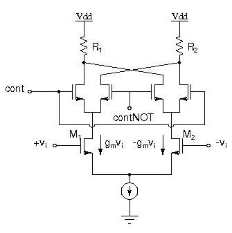
 

I'm not sure what's meant by CMOS current mode VGA, but attached, you can see how the two diff pairs control the gain of the amplifier by steering the small signal current going to the load resistors.

As you know, the single sided output is gm.vi * Rload, so if you steer some of the -gm.vi (from M2) to add up with the gm.vi (from M1), then you have reduced the output signal and hence you have reduced the gain.

I guess the design parameters are the range of the gain and the corresponding range of control signal.


17_1169722357.jpg
 
but if the input signal is a current signal, if I would like to use the input current signal to tune the gain of the amplifier?
 

i guess 'current mode' is a new mode of representing your signal(instead of voltage)....
correct me kartin, if i m wrong?

-
Manu
 

I think you can first change the current signal to voltage signals, and then use voltage VGA design tech.
 

tarun_taurus said:
i guess 'current mode' is a new mode of representing your signal(instead of voltage)....
correct me kartin, if i m wrong?

-
Manu


yes, the current signal is used to control the gain of the amplifier
but the actual input signal is still voltage signal which will be amplified
 

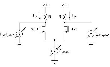
I'm not an expert in that type of AGC, but here is an idea that might be useful to you:

By varying the tail current, the transconductance of the input pair will vary and hence the small signal gain will vary, It is a nonlinear relation though.

However, to keep the output common mode fixed, you have to inject an amount of current in the load resistors equal to the gain control current and the desired output current.

4_1169791687.jpg
 

How if it is a current signal?
 

Lookup the current amplifier, perhaps it is helpful.
 

The simplest VGAs I can think are:
1) If I-V, then you can try transimpedance Amp and
vary the R to get different gain,
2) For I-I, the simplest amp is the current mirror,
you can switching in and out banks of mirrors to
change the ratio, then.
 

In razavi's book
you can get lot fo information!
 

The standard way seems to be to switch transistors in a current mirror. check this ref as an example of continuous tuning.
 

If you mean this kind of VGA is linear in dB and the outputs controled by the input difference of current, I read some papers about the function of (1+x)/(1-x)=e^2x,
sometimes some one will use the current to fulfil this function,for example (I+I1)/(I-I1), the ratio of I1/I is the same meaning of x.
 

Hi,
Just like what megzhuy said, there are IEEE papers about that VGA which take use of the function, (1+x)/(1-x)=e^2x, which realized the gain veriation and meanwhile the dB-linear gain characteristic, it's a good method to realize a current mode VGA.
and for this type of VGA, you can refer to this paper: A low-power CMOS VGA for 50 Mb/s disk drive read channels, by R. Harjani.

And for the topology jonashat suggested, I don't think it work as an VGA, but it's a mixer, if you want to make this gilbert structure to be an VGA, you should add the differential control signal on the lower pair while add the input signal on the upper two pairs, by tuning the control voltage, the current following through the loads is tuned to realize variable gain. You can get the detailed explaination in the razavi's book.

Hope it helps!
 

Status
Not open for further replies.

Part and Inventory Search

Welcome to EDABoard.com

Sponsor

Back
Top