Continue to Site

Welcome to EDAboard.com

Welcome to our site! EDAboard.com is an international Electronics Discussion Forum focused on EDA software, circuits, schematics, books, theory, papers, asic, pld, 8051, DSP, Network, RF, Analog Design, PCB, Service Manuals... and a whole lot more! To participate you need to register. Registration is free. Click here to register now.

At89c52, 0-to-1 transition in T2EX

Status
Not open for further replies.

Help

Advanced Member level 2
Joined
Feb 15, 2005
Messages
617
Helped
7
Reputation
14
Reaction score
3
Trophy points
1,298
Activity points
7,065
it0 in at89c52??

Hi,

At89c52 EXEN2 is set, a 0-to-1 transition in T2EX. Is it posible? If not how can we do?

I got incoming signal which is "10" and "01" for 10=ZERO and 01=ONE. How can i verify this to two signal in my code?

Please guide me in C program.

Thank You.
 

T2EX pin can be only used to detect 1-to-0 transition ..
If you need to detect 0-to-1 transition put the incomming signal through inverter ..

Set EXEN2 to 1 and enable TIMER2 interrupt ..
Each 1-to-0 transition on T2EX pin will activate TIMER2 interrupt ..

But ..
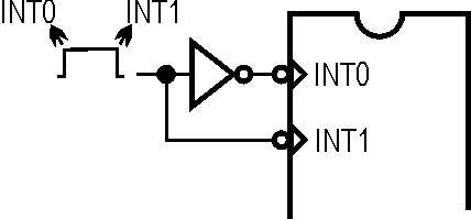
If you can, connect this incomming signal to INT0 and inverted to INT1 (set IT0 and IT1 - edge triggered interrupts) ..
Transition 1-to-0 will activate interrupt0, transition 0-to-1 (inverted to 1-to-0) will activate interrupt1 ..

Regards,
IanP
 

    Help

    Points: 2
    Helpful Answer Positive Rating
Hi,

Which's mean we have to methods to solve it rite?

M1) One-Interrupt
If you need to detect 0-to-1 transition put the incomming signal through inverter ..
Set EXEN2 to 1 and enable TIMER2 interrupt ..
Each 1-to-0 transition on T2EX pin will activate TIMER2 interrupt ..
But i not so understand about here. If i put a inverter to invert the incoming signal so i only can receive 0-to-1 signal all the time. but how bout 1-to-0?

M2) Two-Interrupt
If you can, connect this incomming signal to INT0 and inverted to INT1 (set IT0 and IT1 - edge triggered interrupts) ..
Transition 1-to-0 will activate interrupt0, transition 0-to-1 (inverted to 1-to-0) will activate interrupt1 ..
If we use this method we have to use 2 external interrupts Interrupt T0 and T1 (/INT0 and /INT1). So i have to connect this to pin together rite?

Thank You.
 

M1 can not be used to detect two different transitions ..

M2: see picture below .. signal to Int0 is in the same phase as the input signal, you can use only one inverter to invert signal to Int1 ..
If you don't want to use inverter gates you can use one digital transistor - transistor with build-in base resistor(s), that is ..
**broken link removed**

Regards,
IanP
 

EXEN2 is set, a 0-to-1 transition in T2EX will generate interrupt
IT0 or IT1 is set, a 1-to-0 tramsition in INT0 or INT1 will generate interrupt
connect you signal source to T2EX & IT0 or T2EX & IT1 will solve you problem without external inverter!
 

Prove me wrong, but all three pins (/INT0, /INT1 and T2EX) can only detect 1-to-0 transition, so an inverter is necessary ..

Regards,
IanP
 

hI,

budhy said:
EXEN2 is set, a 0-to-1 transition in T2EX will generate interrupt
IT0 or IT1 is set, a 1-to-0 tramsition in INT0 or INT1 will generate interrupt
connect you signal source to T2EX & IT0 or T2EX & IT1 will solve you problem without external inverter!


I never play the externer interrupt before.
For the internal diagram show us, is it initial we have to set the IT0=0 (or IT1=0) then it will switch to internal inverter.

Condition: 0-to-1 transition
EX0 = interrupt will set
ET2 = no interrupt

Condition: 1-to-0 transition
EX0 = no interrupt
ET2 = interrupt will set


Thank You.
 

Condition: 0-to-1 transition
EX0 = interrupt will set
ET2 = no interrupt

This won't work ..
All pins can detect only 1-to-0 transitions ..
You need an inverter on one of these pins ..

Regards,
IanP
 

    Help

    Points: 2
    Helpful Answer Positive Rating
Hi IanP,

You are right. Even though we set the IT0=0 (use internal inverter) we also have to 1-to-0 transitions, otherwise if incoming signal is LOW all the time the interrupt will be occurs constantly.

My problem now is like that.
Let say i have incoming data is 16 bits decoded it back to 8 bit byte... "10" gets turned back into a zero and "01" gets turned back into a one.

How am i going to use intterupt detect the alter incoming signal? Do you have ideas?

Thank You.
 

May be this is your final solution :
Code:
State   bit   0
;
    ORG   0x0000
    AJMP  Start
;
;*** INT0 Interrupt Service Routine
;
    ORG   0x0003
    SETB  State         ; it is '1'
    SETB  EXF2          ; transition occured
    RETI
;
;*** INT1 Interrupt Service Routine
;
    ORG   0x0013
    CLR   State         ; it is '0'
    SETB  EXF2          ; transition occured
    RETI
;
;*** Transition detected (Timer 2 Interrupt Service Routine)
;
    ORG   0x0023
;   do some thing here
    CLR   EXF2
    RETI
;
;*** Main Program
;
Start:
    SETB  EX0
    SETB  EX1
    SETB  ET2
    SETB  EA
Here:
    SJMP  Here

77_1169007895.gif
 

    Help

    Points: 2
    Helpful Answer Positive Rating
In the Manchester encoding shown, a logic 1 is indicated by a 1 to 0 transition at the centre of the bit and a logic 0 is indicated by a 0 to 1 transition at the centre of the bit. Note that signal transitions do not always occur at the 'bit boundaries' (the division between one bit and another), but that there is always a transition at the centre of each bit.

To decode manchester coded string you have to synchronize one of microcontroller timers with the incomming string and read transition between each bit's boundary ..
On the attached picture you have to detect edges marked with a short horizontal line (it is the centre of the original bit) - not the other ones ..
In this example the codded message is: 110100

Regards,
IanP
 

    Help

    Points: 2
    Helpful Answer Positive Rating
Hi,

To decode manchester coded string you have to synchronize one of microcontroller timers with the incomming string
How i goin to do that? How to receive the transition data? Please guide me somemore...

How can i receive this codded message 110100 in my Microcontroller?

I already prepare the code for decoder but don't know it usefull not. :cry:

Code:
for(nbit=0; nbit<7; nbit++) // 1 byte
{
   If(codeMsg[nbit*2]==0 && codeMsg[nbit*2+1]==1)
   {
      decode[nbit] = 1;
   }
   else
   {
      decode[nbit] = 0;
   }
}

Thank for your help.
 

I'm not going to discuss the appropriateness of interrupts to decode manchester or any other encoded stream, this is just on possibility of both edge interrupt, under certain conditions:
**broken link removed**

wek
 

    Help

    Points: 2
    Helpful Answer Positive Rating
Hi,

Thank for everyone. Now i already sloved the decode manchester and the decode coding.

Thank You.
 

Status
Not open for further replies.

Part and Inventory Search

Welcome to EDABoard.com

Sponsor

Back
Top