david119
Junior Member level 2
Hi everyone,
I want to connect a machXO fpga (3.3V) to an atmel parallel EEPROM memory chip (3.3.V)via a bus.
Here are the data sheets:
machXO fpga
http://www.latticesemi.com/dynamic/...w_documents&document_type=32&sloc=01-01-02-00
Atmel EEPROM
**broken link removed**
I am fairly new to fpga’s and inexperienced, so I decided to start with a small test circuit to establish that the fpga’s high ‘Z’ outputs would not produce any bus contention. I wrote four Tri_state_buffer’s in VHDL. The main line of the code is:
data <= input when (oe = '1') else 'Z' ;
There are four data inputs and four oe’s are connected to eight external DIP switches. Data1, data2, data3, and data4 are the outputs from the VHDL modules and are tied to four separate output pins on the fpga. Then all four outputs are tied together and attached to one data bus line. Also on the data bus is one LED to display the output.
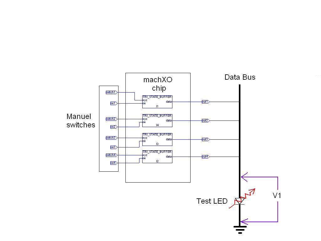
Everything seems to work fine with the LED. If one OE is enabled and the corresponding input switch is toggled back and forth the LED goes on and off as should be expected. The voltage measurements at V1 go from 0V to 2.05Volts with the LED in place. If I remove the LED the voltages go from 0 to 3.3Volts.
The problem that I don’t understand occurs when all the oe’s are disabled and the outputs are in the high ‘Z’ state. The LED remains off, however if I measure the voltage with the LED in place V1 = 1.7Volts and with the LED removed V1 = 3.3Volts.
-- I thought a high ‘Z’ state meant high impedance or like an open circuit?
-- I’m worried that when I finally do connect the fpga to my memory chip these voltages
will cause bus contention and corrupt the data that I want to store. Is this a legitimate concern?
Thanks in advance for your input
I want to connect a machXO fpga (3.3V) to an atmel parallel EEPROM memory chip (3.3.V)via a bus.
Here are the data sheets:
machXO fpga
http://www.latticesemi.com/dynamic/...w_documents&document_type=32&sloc=01-01-02-00
Atmel EEPROM
**broken link removed**
I am fairly new to fpga’s and inexperienced, so I decided to start with a small test circuit to establish that the fpga’s high ‘Z’ outputs would not produce any bus contention. I wrote four Tri_state_buffer’s in VHDL. The main line of the code is:
data <= input when (oe = '1') else 'Z' ;
There are four data inputs and four oe’s are connected to eight external DIP switches. Data1, data2, data3, and data4 are the outputs from the VHDL modules and are tied to four separate output pins on the fpga. Then all four outputs are tied together and attached to one data bus line. Also on the data bus is one LED to display the output.
Everything seems to work fine with the LED. If one OE is enabled and the corresponding input switch is toggled back and forth the LED goes on and off as should be expected. The voltage measurements at V1 go from 0V to 2.05Volts with the LED in place. If I remove the LED the voltages go from 0 to 3.3Volts.
The problem that I don’t understand occurs when all the oe’s are disabled and the outputs are in the high ‘Z’ state. The LED remains off, however if I measure the voltage with the LED in place V1 = 1.7Volts and with the LED removed V1 = 3.3Volts.
-- I thought a high ‘Z’ state meant high impedance or like an open circuit?
-- I’m worried that when I finally do connect the fpga to my memory chip these voltages
will cause bus contention and corrupt the data that I want to store. Is this a legitimate concern?
Thanks in advance for your input