Youncen
Member level 2
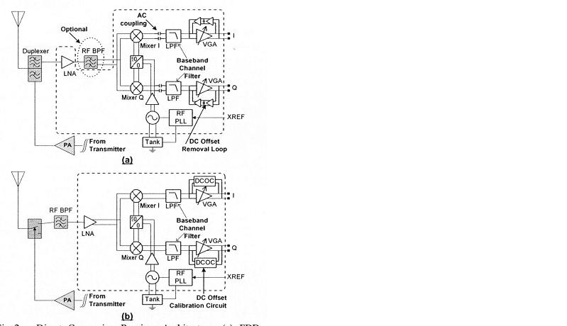
zero if dc offset
someone tell me that the dc offset is detemined by the layout qualitfication.
I think this will be controlled not solve,but how?
someone tell me that there are some digital calibration technique to control the bias?but this maybe too complicated a technique.
can anyone offer some details of the dc offset calibration technique in the picture.
(ac coupling or feedback integrator/dc servo-loop or other....)
thankS, and again thank you.