Continue to Site

Welcome to EDAboard.com

Welcome to our site! EDAboard.com is an international Electronics Discussion Forum focused on EDA software, circuits, schematics, books, theory, papers, asic, pld, 8051, DSP, Network, RF, Analog Design, PCB, Service Manuals... and a whole lot more! To participate you need to register. Registration is free. Click here to register now.

Help me out with my opamp simple design

Status
Not open for further replies.

cimo

Newbie level 6
Joined
Oct 27, 2006
Messages
12
Helped
0
Reputation
0
Reaction score
0
Trophy points
1,281
Activity points
1,387
Hi
this is my first post so i d like to say HELLO to everybody

i have a fair experience in electronics i can solder etc but i can t design any circuit.
Here the circuit i need:
i have a sensor that will output from a little above 0 to 2,4/2,5 volts.
I need to scale this value from 0 up to 5 volts.The sensor also has a little jittering so i d like to fix that as well.

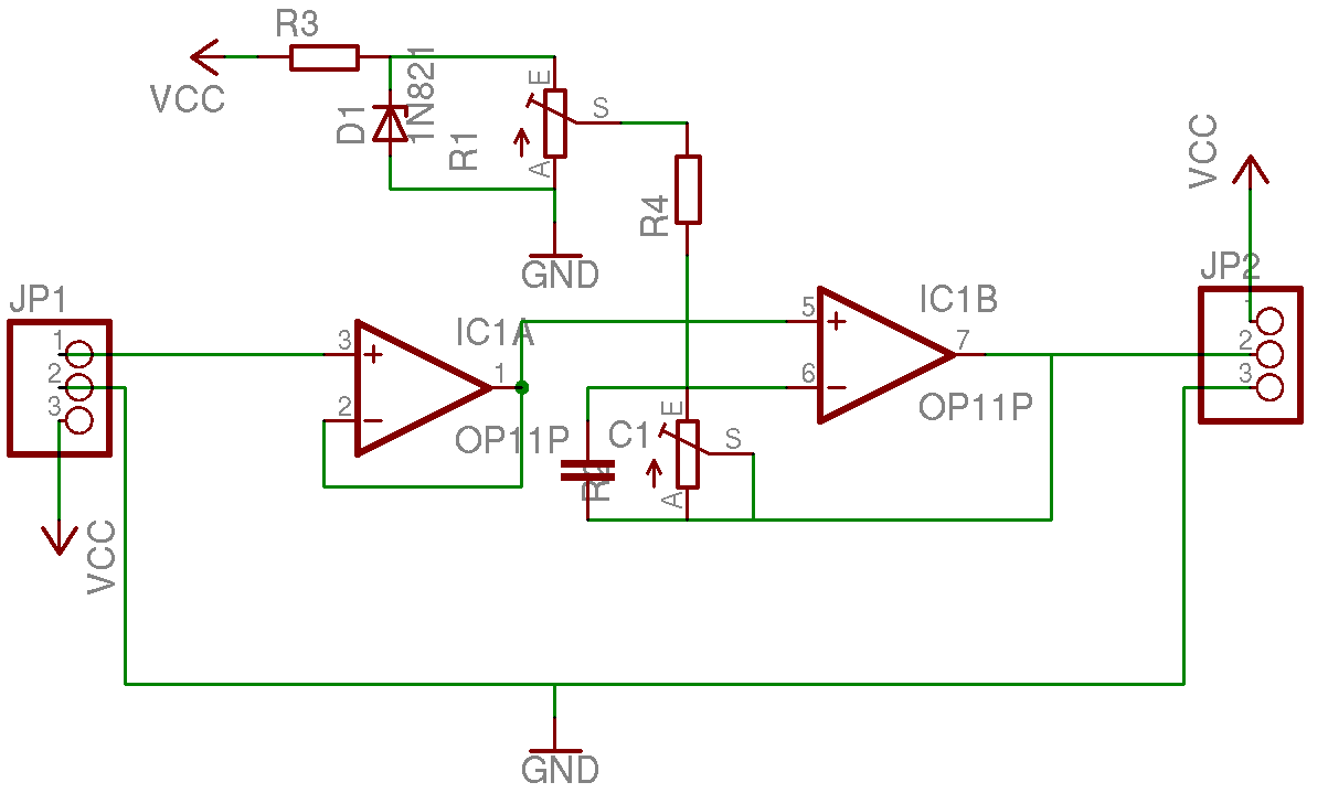
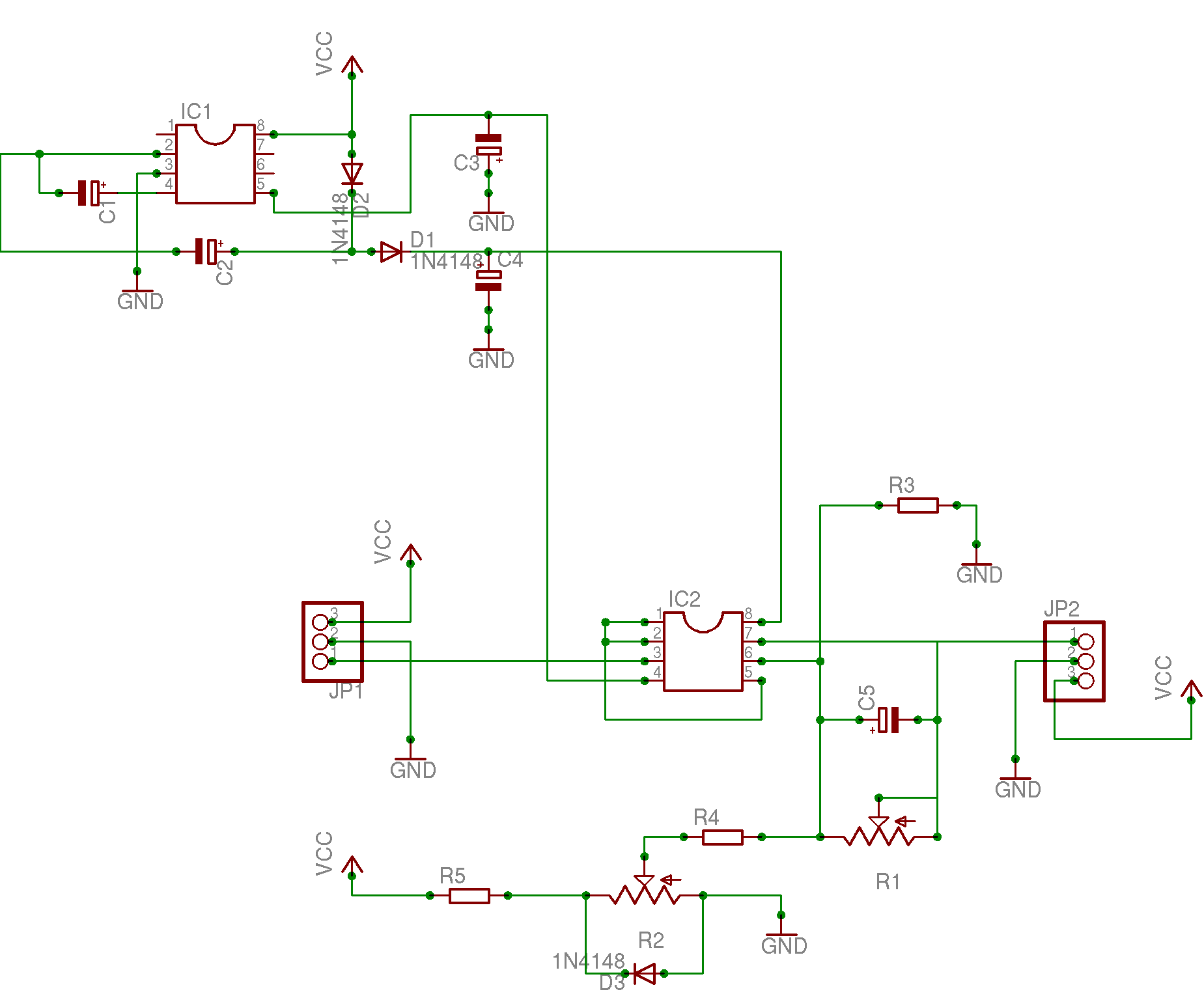
The basic circuit i need is an Opamp that will double the voltage i am feeding to it but the ideal would be to be able to have a trimmer that will let me multiply the voltage in the input from x1 to x3.
The second step would be to have an offset trimming feature to have a 0 volt starting point
The third step to fix the jittering problem (but maybe an Opamp wil already do that)

Could anybody point me to right direction? Maybe for some of you this is just a very easy design.Which IC do you reccomend?

Thanks
Simone
 

lm358 eagle

Hi !

Any general purpose Operational Amplifier will help you. Try the easy to find LF411, TL071, even the LM741. Check the datasheets for circuits configuration, specially the non inverter amplifier (basically you enter your signal in the positive input pin, a resistor connecting the output pin to the negative input pin (it can be a potentiometer or trimpot), another resistor connecting the same negative input pin to ground and a trimpot in the offset pins. This configuration allows you to have a positive gain. If you want a gain of 2, just do the both resistors the same value (e.g. 10kohm, one of them may be a trimpot of 20kohm to adjust the gain).
 

eagle lm358

You can try this circuit. The gain is adjusted with R1 between 1 and 3. The cap C1 can be selected to give you the required rejection (probably in the tens of nF range).

As for the offset, it can be adjusted with R2, but only in the negative direction. Note that the output of the opamp cannot go negative, unless you power it using a negative source (connect pin 4 to a negative voltage. This is actually advisable, since this opamp cannot drive its output all the way down to the potential of pin 4.

+VREF should be a very stable voltage, of say 1~2.5V. A suitable reference diode would be LM385-1.2 or LM385-2.5, or TL431 for example.
If you need to adjust the offset in the positive direction, too, then the right end of R2 should be connected to a clean negative reference, which can be obtained with another reference diode from the negative voltage that supplies pin 4of the opamp.

Note that if you use a negative supply voltage, the left pin of R3 should still be connected to ground, that is the common point of the positive and negative sources. Only pin 4 of the opamp gets connected to the negative supply.
 

op amp charge pump

Fantastic, thanks guys for the quick response.
Before getting your messages i ve designed a circuit : see the attachment.I ve also forgot to tell that i will feed the circuit with 5 volts, will vvv s circuit work as well with 5 volts?
I am planning to have a first stage to lower the impendance as you can see on the attachment.
LM358 is not the actual choice i was thinking about LM324
+VREF should be a very stable voltage, of say 1~2.5V. A suitable reference diode would be LM385-1.2 or LM385-2.5, or TL431 for example.
is a reference diode a voltage regulator? is it also called zener diode?

txxxx
simone
 

eagle opamp

hey
here the new schematic with zzz s idea and the added first stage.
 

charge pump opamp

The only thing that is not right is the offset adjustment. The Zener should be in parallel with the offset adjustment pot, anode to GND, and there should be a ballast resistor from the cathode of the Zener to Vcc.

The circuit will not work with 5V only, bacause the LM358 is not a rail-t-rail input opamp. It needs at least 2V from each input to Vcc, so that woul make the minimum Vcc=7V.

The output is not rail-to-rail either, so the output will not go to zero volts when the input is zero. Therefore, I recommend you use a negative voltage for the opamp, even if it's only -1.5 ~ -5V.
On the other hand, you said the sensor outputs "from a little above zero", so the circuit may still work without a negative voltage, depending on how much "a little above zero" actually is.
 

lm358 eagle library

hi
again thanks for the support, i ve attached the new schematic
58_1162250230.png

LM358 is not my choice: i ve just picked up a quad opamp from Eagle library, i will try the LM324: it should work with a positive 5 volts and i need a negative offset of about 0,25-0,5 volts.
About the supply i really have to try to use just the 5 volts, i could eventually use a 9 volts battery but i fear that a charge pump to get negative voltage will disturb the sensor.
Thanks
simone
 

op amp offset adjustment

Hi Simone,

Yes, you got it right. By the way, LM358 is actually identical internally to the LM324, except it only has 2 opamps, so it is not a rail-to-rail opamp.

I understand you need to power the sensor from a 5V supply. I think you should use a higher voltage, say 9~12V, and a 5V regulator to power the sensor. Then use a charge pump to produce a negative voltage for the opamp and the offset adjustment circuit.
Use the same 9~12V voltage to power the opamp's +Vcc. Because the sensor is powered through a regulator, there should not be any problems, the regulator should reject the noise produced by the charge pump. And 9V for the opamp's Vcc will give you enough headroom to obtain 5V at the output, without any concerns for clipping.

Regards,
Victor

P.S. Your schematic does not show all the dots, so perhaps you have some bad connections (for example the gain adjustment pot does not seem to be connected). Try redoing them.
 

tl071 eagle library

hi
since i can t get more then 5 volts from my circuit and would like not to add a battery to the sensor, i thought i could put a charge pump after Vcc to boost up to around 10 volts and then invert the voltage (if i can t get hold on a opamp with only + supply)(OPA350?)
Here:
the link to the new post about the charge pump
thanks
simone
 

lm358 en eagle

Hi Simone,

If you can find an ICL7662, you could solve the problem. Take a look at the circuit, which came from page 10 of the Intersil datasheet.
It produces both -5V and +10V, using only a few components.

VVV
 

eagle opamp power supply

right back from the shop: they don t have any smps dc/dc converters ... just a few opamps... so either i will order from farnell/conrad but that will cost me more on shipping than materials, or wait or look for something else for example i have found a 7660 at home and can try to do something with it ... this is what it means to live in a small island in the middle of the ocean.... any help appreciated...
simone
 

voltage regulator opamp schematic

hi
so here we go with a schematic adapted to what i ve found here at home: aTL082 and a 7660 (seems to be same as 7662)

82_1162734152.png


R1 Trim 200K
R2 Trim 200K
R3 100K
R4 100K
R5 ?
C1,2,3 10 microF
D1,2 ?
D3 Zener 2,5 volts
IC1 7660
IC2 TL082
JP1 IR Sharp sensor
JP2 I/O +5 volts Vcc

i have a doubt about which kind of diodes to use on the voltage booster (1n4148?) and the value for the "ballast" resistor.I look forward to receive an OK from somebody and make the PCB.
Thanks
simone
 

simple op amp circuit to multiply voltage step up

For fixing jittering, the generic solution is using the delay circuit, it consists of a resistro and a cap.

To get the -V from the +V, beside using ICL7662, you can use MC34063 from ON semi, very popular now, for any purpose of power supply.

In the worst case, if you need a very small power for Opamp from -V, you can use a CMOS, for example 4011, to make a generator from +V, and then use a rectifying circuit to get -V. So, it is easy to make.

nguyennam.
 

Status
Not open for further replies.

Part and Inventory Search

Welcome to EDABoard.com

Sponsor

Back
Top