Continue to Site

Welcome to EDAboard.com

Welcome to our site! EDAboard.com is an international Electronics Discussion Forum focused on EDA software, circuits, schematics, books, theory, papers, asic, pld, 8051, DSP, Network, RF, Analog Design, PCB, Service Manuals... and a whole lot more! To participate you need to register. Registration is free. Click here to register now.

Proteus users please help... Picbasic Pro "blink"

Status
Not open for further replies.

itsallgood

Member level 2
Joined
Mar 15, 2002
Messages
48
Helped
0
Reputation
0
Reaction score
0
Trophy points
1,286
Activity points
329
picbasic pro proteus

Hi guys,

I've just managed to compile one of the examples that come with picbasic pro, the "blink" example,

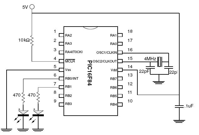
anyway, i've put it into a pic 16f84a in Proteus, but i cannot seem to wire it up to actually make the led blink.

I can see the little leg changing from red to blue, but i cannot wire up the battery, L.E.D and chip.


**broken link removed**


Can somone please help.

Regards.
 

add ground connection in proteus

I think ur design is runing. first stop then wire up. it has huge sample, look at attach
 

picbasic pro y proteus

sorry, your picture will not load?

I cannot seem to find a way to wire up my circuit, and make the led light up.
 

sample picbasic pro

Hi ill help you


your program is activating the i/o at pin B0 {its red}

but it isnt connected to the led

the led needs the one end to the i/o b0 and one end to ground {anode}

you need to add a ground connection to the sheet {the menu on the left hand side called .... connections click the box click ground and add the connection}
now wire up the led
and run again

BUT for this type of simulation you need to use a digital led or you need to add a pullup resistor


maybe you need to study the circuit from pic basic and wire the same

i beleve this example is also already in the samples dir of the proteus folders


a quick look at the examples there will set you in the right path for sure


have a look over it and also try to open the help files up {i used two monitors to do this {and now use three}}

the help files youll need to refer to constantly reading each function as you use it

and try it by example

if you get stuck post a .dsn file or a .sec file and get more help
 

proteus picbasic pro

Hi,

thanks for the reply, but i dont understand what the "ground connection" is for???

Say i really built this circuit, and i wanted it to run off batteries, there wouldnt be a ground connection. So how would you connect it up then? with a battery.

Thanks so much.

Regards.
 

how to add ground in proteus

to itsallgood:
when u say GROUND, it refers to a common refernce point of zero potential in the circuit. It does not refer EARTH. And quite similar to COMMON but not the same. although u r running DC direct from the batery, u do not say you are using "-"tive as there is only high and low in DC. u will have 9V when u refer positive 9V to 0V(GND). and not negative 9V, then u would have 18V(IF its AC) and 0V(IF its DC) due to the different voltage potentials.
So in short, u refer GND as a place where HIGH voltage potential moves to the LOW voltage potential. else there wont be any current flowing in the first place.
In your case, "-"ve is connected to GND.

ps: do correct me if im wrong.
 

    itsallgood

    Points: 2
    Helpful Answer Positive Rating
proteus how to put battery and gnd

fms!! Thanks so much, for some reason i thought "ground" was earth -- like in radios. d'oh.

So, now i can see my LEDs light up!! yay :) look at them go lol.

**broken link removed**

Now i have it working in proteus, can someone tell me if my circuit in paint would be the correct way to wire it up in the real world? I carnt wait to build my first pic circuit board :)

**broken link removed**
 

Re: Proteus users please help... Picbasic Pro "blink&am

Thats nice. But its recommended for u to connect a resistor in series with the LED. Around 330Ohm to 470Ohm will do. then u have to connect a 4MHz Crystal(Oscillator) to osc1 and osc2 with 2 filtering cap. around 22pF. Else u can simply use 4MHz resonator.
N Oops, don forget bout the MCLR pin. pass 5V trough 4k7-10kOhm resistor before entering the pic. all sources to pic is 5V. not 9V.
83_1157814854.JPG
 

    itsallgood

    Points: 2
    Helpful Answer Positive Rating
thanks so much fms, thats the best help i've got on eda :)

I've got a decent diagram to build from now -- i dont really understand what all the new parts are for, but if you say i need them i guss i do.

I'm going to order all these parts now, so hopefully i can build the circuit on tuesday.

Can you also please tell me what the software you used to do that diagram? it looks well better then my proteus screen dumb, and my "paint" picture lol.

Cheers.
 

Re: Proteus users please help... Picbasic Pro "blink&am

thanks so much fms, thats the best help i've got on eda

U r most welcome :)

:) actually i did that with paint :p did some come cutting, editing n pasting the diagram from an ebook. maybe u can try out multisim 9 instead. never tried that for PIC sim though. good luck.
mayb u can get some ebooks for PIC. basics are there. u can gain a lot from there. n some have many sample circuits. happy searching :)
 

Re: Proteus users please help... Picbasic Pro "blink&am

i just test the proteus
 

Re: Proteus users please help... Picbasic Pro "blink&am

so how was it? is it working.
 

Status
Not open for further replies.

Part and Inventory Search

Welcome to EDABoard.com

Sponsor

Back
Top