Continue to Site

Welcome to EDAboard.com

Welcome to our site! EDAboard.com is an international Electronics Discussion Forum focused on EDA software, circuits, schematics, books, theory, papers, asic, pld, 8051, DSP, Network, RF, Analog Design, PCB, Service Manuals... and a whole lot more! To participate you need to register. Registration is free. Click here to register now.

Frequency response of a high-pass active filter using LM741

Status
Not open for further replies.

powersys

Advanced Member level 1
Joined
Nov 29, 2005
Messages
439
Helped
3
Reputation
6
Reaction score
2
Trophy points
1,298
Activity points
4,981
lm741 bandwidth

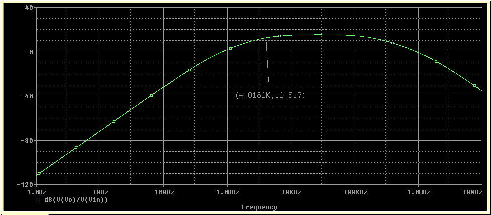
The circuit shown is a 2nd-order high-pass active filter using LM741. The frequency response of the filter is given in another figure below. Why does the gain (dB(Vo/Vin) of the filter start to drop again after 100kHz? For an ideal high-pass active filter, the gain after cut-off frequency should remain constant, right? Please advise. Thanks.
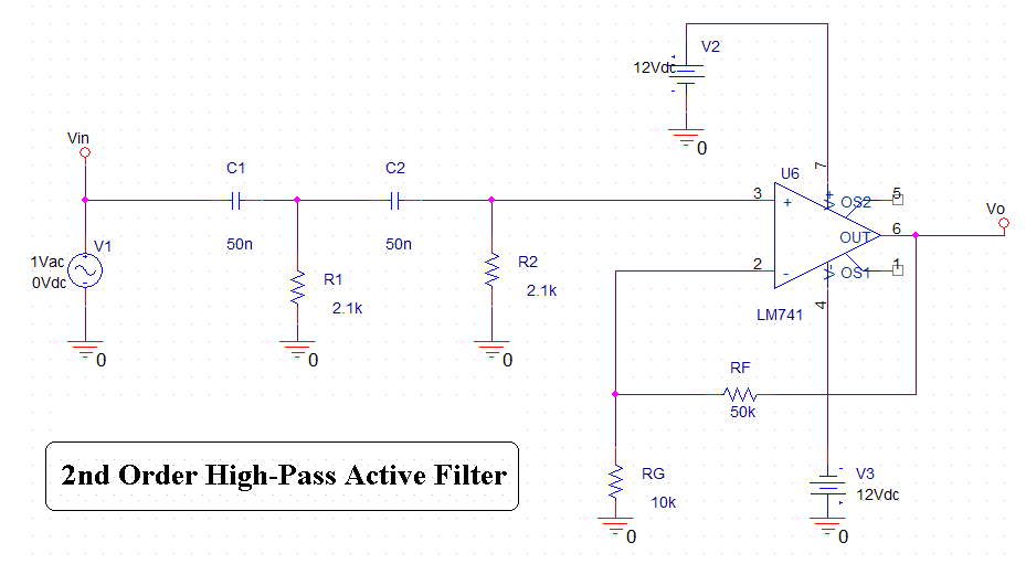
highpassfilter.gif


freresponse.gif
 

active filter frequency response

This is because you use LM741 ..ee its data sheet for its frequency response ..
If you used an opamp rated for,say, 100MHz, then nothing the story will be different and your High-Pass Filter frequency response will be flat to as far as almost 100MHz ..

Regards,
IanP
 

lm741 low pass filter

IanP said:
This is because you use LM741 ..ee its data sheet for its frequency response ..
If you used an opamp rated for,say, 100MHz, then nothing the story will be different and your High-Pass Filter frequency response will be flat to as far as almost 100MHz ..

Regards,
IanP

Besides the opamp, do you think the type of capacitor that we use in practical circuit will alter the shape (e.g. become not flat after certain frequency) of the frequency response? If I'm not mistaken, some types of capacitor are good in certain frequency range, but some are good in other certain frequency range, right? Pls correct me if I'm wrong. Thanks.
 

lm741 high pass filter

You are right, of course :D:D:D ..
Real capacitors are not ideal, so are resistors, inductors and all other components ..
Also a PCB itself, or a breadboard, or whatever you use to assembly a circuit will have unwanted reactances (capacitance and inductance) which will affect the flatness of the frequency response of a circuit ..

Regards,
IanP
 

high pass filter frequency response

IanP said:
You are right, of course :D:D:D ..
Real capacitors are not ideal, so are resistors, inductors and all other components ..
Also a PCB itself, or a breadboard, or whatever you use to assembly a circuit will have unwanted reactances (capacitance and inductance) which will affect the flatness of the frequency response of a circuit ..

Regards,
IanP

I see... Thanks. Would you please recommend the types of capacitor that are suitable for filter design?
 

lm741 response

Hi,

There are two aspects of the problem:
1.)Every opamp has a parameter named GBW (Gain-Bandwidth product). Due to the fact that this product is constant, with the increase of the gain you'll found a corresponding decrease of the bandwidth. Usually the bandwith of an opamp is specified at unity gain. According to the datasheet, the LM741 has a GBW somewhere between 475KHz and 1.5MHz. In your case, the gain of the filter is 6. Gain = 1+(RF/RG). Now, you can calculate the overall bandwidth of your circuit. This is for real circuits.

2.) As far as I know, the AC analisys in spice don't take into account the DC gain of the circuit. The bandwidth of any circuit is specified at -3dB, so if you take a closer look you'll find that the circuit is around 1.5MHz, that corresponds to the datasheet value.

Best Regards
 

    powersys

    Points: 2
    Helpful Answer Positive Rating
741 unity gain frequency

Thanks for you reply... Very interesting explanation...

x_zoli said:
1.)Every opamp has a parameter named GBW (Gain-Bandwidth product). Due to the fact that this product is constant, with the increase of the gain you'll found a corresponding decrease of the bandwidth. Usually the bandwith of an opamp is specified at unity gain. According to the datasheet, the LM741 has a GBW somewhere between 475KHz and 1.5MHz. In your case, the gain of the filter is 6. Gain = 1+(RF/RG). Now, you can calculate the overall bandwidth of your circuit. This is for real circuits.
What do you mean by "... the overall bandwidth of your circuit?

x_zoli said:
2.) As far as I know, the AC analisys in spice don't take into account the DC gain of the circuit. The bandwidth of any circuit is specified at -3dB, so if you take a closer look you'll find that the circuit is around 1.5MHz, that corresponds to the datasheet value.
What's the DC gain of the circuit? How does the DC gain of the circuit will alter the '... bandwidth of any circuit is specified at -3dB...'?

Thanks.
 

lm741 open loop gain

The overall bandwidth means the frequency domain where the circuit has a response greater than -3dB.

The DC gain is the closed loop gain calculated for the used amplifier. In this case, having a non-inverter opamp, the gain will be given by G = 1+(RF/RG). For this case, RF = 50Kohm, RG = 10Kohm, resulting in a gain of 6. The term DC gain is used because it represents the highest gain the amplifier can achieve in a given closed loop.

For the given filter and the given amplifier: you have GBW=1.5MHz and G=6. In the real life, you'll get BW = GBW/G = 250KHz.

Best Regards
 

    powersys

    Points: 2
    Helpful Answer Positive Rating
what does lm means in lm741 op amp means

x_zoli said:
2.) As far as I know, the AC analisys in spice don't take into account the DC gain of the circuit.
I don't understand this sentence... would you pls elaborate a bit more, e.g. relate to the graph shown in my first post?


x_zoli said:
For the given filter and the given amplifier: you have GBW=1.5MHz and G=6. In the real life, you'll get BW = GBW/G = 250KHz.
Can we 'determine' the BW from the frequency response graph as shown in my first post? If YES, is the BW shown in the graph 250kHz?

Thanks a lot...
 

frequency response of active high pass filter

Hi,

as I said in the first post, there are two approaches - the real life approach and the simulation. The LM741's datasheet says that the GBW is 1.5MHz. If you look at the frequency response (beware, it's logarithmic), you'll se that the frequency value corresponding to -3dB is around 1.5MHz. You'll get the exact value from O*cad. Now, this is the simulation. In the real life, the bandwith of almost any amplifier will decrease with respect to the gain of the amplifier (as i said in the second post). That's why in most of the cases, especially where large bandwidth is required, more amplifier stages are used, each of the amplifiers having a smaller gain.
So, there is no problem with your simulation, just that it won't work in practice as you would expect.

Best Regards
 

activefilter used ic 741

As I understand it, according to datasheets I've read, open loop gain is what you need to look at, as the open loop gain (the gain of the op amp without any feedback) curve (always a negative sloped graph) determines what is and is not possible frequency-wise.

Where we're (even though I didn't say it) saying DC gain, what we're pointing at is the gain at 0 hz, the far leftmost Y value at the lowest X value of the open loop gain plot/curve/graph.

Likewise, when we talk of a gain-bandwidth product, we're literally talking about the product of gain times the bandwidth, hence the name.

On the 741 (a very general purpose low frequency op amp), the open loop gain (that negative-sloped graph mentioned above), you'll see that the gain falls to unity somewhere in the megahertz (1 to 2 I think.) What this means is, the best CLOSED LOOP gain you can do is 1 if you want to output 1.5 Mhz (just picking a number) across a load. However, there's more to it than that. As I seem to remember that running an op amp at such limits is highly unrecommended, but I don't remember why. Suffice it to say, expect little in the high end if you use the 741 with any kind of gain. It's a general purpose amp that'll handle to audio frequencies ok, but that's about it.

Also, I notice that your second order filter (two poles in the transfer function, the denomnator's zeroes) is using equal components. You do realize that you've not designed a 2nd order filter at fc=N but rather a 2nd order at fc=<<N, right?

I must confess that I'm a EET, but I do know that transfer function factors form a polynomial. One section multiplied by another section changes the overall polynomial, and the overall polynomial describes the frequency response. You can't just line up two of the same RC filter and expect the same cutoff frequency. It's not that simple. In fact, if I understand (and I am constantly learning!), you determine the polynomial (Butterworth, Chebychev, Bessel, Elyptic, that's all I remember) you want and then factor it to find the RC sectons. Then you play with the values from this core design to get the match that gives you the response you want.

I know you didn't ask all that, but I thought I'd menton it, because I actually have time to speak today. :)
 

    powersys

    Points: 2
    Helpful Answer Positive Rating
frequency response lm741

Plz i need also an example for Frequency response of a Low-pass active filter using LM741 and it`s Ac analysis if u can.

and what is the different if we use high speed op-amp such as AD842
 

filter, high pass, active

asho_234 said:
Plz i need also an example for Frequency response of a Low-pass active filter using LM741 and it`s Ac analysis if u can.

and what is the different if we use high speed op-amp such as AD842
For a higher speed op-amp, then the bandwidth that the op-amp can take will be higher too...
 

741,high pass ckt

The lousy old 741 opamp is 40 years old. It does a poor job with audio because at 20kHz it has hardly any gain to cancel its distortion. Then its distortion frequencies beat together and blur the sound.
Its slew rate limiting reduces its max output swing above only 9kHz.

A TL071 single or TL072 dual opamp cost the same as a 741, are low noise and have full response up to 100kHz. They also have much lower distortion.
 

Status
Not open for further replies.

Part and Inventory Search

Welcome to EDABoard.com

Sponsor

Back
Top