Continue to Site

Welcome to EDAboard.com

Welcome to our site! EDAboard.com is an international Electronics Discussion Forum focused on EDA software, circuits, schematics, books, theory, papers, asic, pld, 8051, DSP, Network, RF, Analog Design, PCB, Service Manuals... and a whole lot more! To participate you need to register. Registration is free. Click here to register now.

What's wrong with the asynchronous counter? Pls advise...

Status
Not open for further replies.

student2005

Member level 3
Joined
Sep 23, 2005
Messages
57
Helped
2
Reputation
4
Reaction score
1
Trophy points
1,288
Activity points
1,793
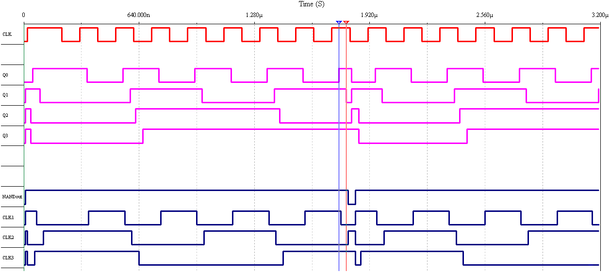
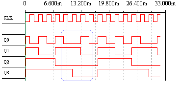
I built an asynchronous counter, as shown in figure below, using Multisim v8.0.45 from Electronics Workbench. The timing diagram of the circuit is given in the 2nd figure below. In my opinion, after 1010 (see circled part), the asynchronous counter should be reset to 1110. But in the simulation result, the output after 1010 was 0010. Would anyone pls advise why? Thanks in advance.
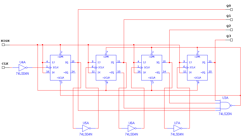
asynctr_5c.gif


asynctr_5c_td.gif
 

So after the state 1010, the next rising clock will change q0 to 1 which subsequently changes q1 to 0. At this point, the output is 1001. When this happens, your NAND gate will set the output to 1110, as you had expected. The problem is that this means that q2 and q3 both see a rising edge (from 1001 -> 1110) and both are toggled again. This leaves the output at 0010. You should see this in your timing diagram if you zoom into the area right after the clock transistion of the 1010 edge.
 

it would be helpful if you also log the signals at the clock inputs of the flip flops.
 

Re: What's wrong with the asynchronous counter? Pls advise..

abdulsalam said:
it would be helpful if you also log the signals at the clock inputs of the flip flops.

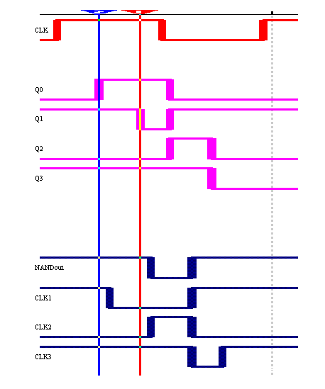
Here is the timing diagram when the frequency of the clock is 10MHz:

asynctr_5c_td_10mhz.gif


asynctr_5c_td_10mhz_zoomed.gif


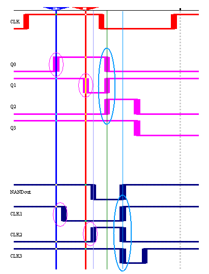
Pls look at the circled portions. When Q0 changes from 0->1 (upper pink circle), after a short interval, CLK1 changes from 1->0 (bottom pink circle). In my opinion, the short interval is due to the propagation delay of the inverter. Pls correct me if I'm wrong.

When Q0, Q1, and Q2 change states (upper blue circle), CLK1, CLK2 and CLK3 take longer interval to change states (bottom blue circle). Why the interval between blue circles is LONGER than the interval between pink circles? I thought they should be same. Why? Thanks.

asynctr_5c_td_10mhz_zoomed_inv_dela.gif
 

Status
Not open for further replies.

Part and Inventory Search

Welcome to EDABoard.com

Sponsor

Back
Top