hebu
Full Member level 4
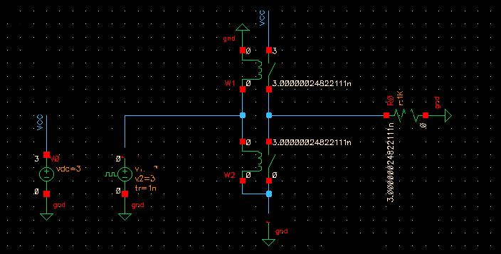
cadence switch
We can find a "switch" in analogLib of cadence, but I don't know why
it can't function as my expectation. So, anybody know do cadence provide
"ideal switch" for simulation purpose?
Thanks,
We can find a "switch" in analogLib of cadence, but I don't know why
it can't function as my expectation. So, anybody know do cadence provide
"ideal switch" for simulation purpose?
Thanks,