Continue to Site

Welcome to EDAboard.com

Welcome to our site! EDAboard.com is an international Electronics Discussion Forum focused on EDA software, circuits, schematics, books, theory, papers, asic, pld, 8051, DSP, Network, RF, Analog Design, PCB, Service Manuals... and a whole lot more! To participate you need to register. Registration is free. Click here to register now.

Capacitor as a MOSFET in RC Circuit

Status
Not open for further replies.

forouzanb

Newbie level 6
Joined
Dec 7, 2019
Messages
12
Helped
0
Reputation
0
Reaction score
0
Trophy points
1
Activity points
84
hi every body
I have a resistor-capacitor circuit that I fitted with MOSFET and want the MOSFET capacitor to phase shift.
Unfortunately, as much as I could increase the amount of this capacitor by increasing the transistor w and l and parallelizing several transistors, I saw no phase difference.
I don't know where my problem is!
Maybe the wrong way to build the capacitor with MOSFETM is wrong
Can anyone help me?
 

Hi,

Before you design .... you should do some considerations and calculations.
What are your expected R and C values?
What's the input waveform?
And what phaseshift (in time) do you expect?

Klaus
 

650/5000
I want to implement a capacitor with MOSFET, which creates a phase difference between the input sinusoidal signal and the output of the circuit. But unfortunately whatever I do, there is no fuzzy difference.
I increased the capacitance as much as possible by increasing and transistor and parallelizing several transistors but no fuzzy difference.
I don't know where my problem is!
What solution would you offer if I wanted to make a phase shift with MOSFET?
My goal is to change the amplitude and phase of the output sine signal relative to the input. I want the output phase of the circuit to be controllable.
For example, I have both a 2 degree phase and a 2 and .....
In general, I want to change the amplitude of the variable resistance signal I make with MOSFET and the circuit phase with MOSFET capacitor.
 

sine wave and input frequency 20hz-20khz
capacitor value is about 10ps
Is it possible for the MOSFET capacitor to be several microns or more?
 

Maybe the wrong way to build the capacitor with MOSFETM is wrong...

You are right here.

Mosfet cannot do anything by itself; it does what it is supposed to do. Usually you tell it what to do by giving a voltage to the gate.

Please provide a diagram with input and output clearly specified. It will be helpful if you also tell what you wanted it to do and what it is actually doing.
 

There is such a thing as a capacitance multiplier. Is that what you made?

Test your RC network by applying a wide variety of frequencies.
Somewhere in the middle is a frequency range which brings out capacitor behavior. You get attenuation and corresponding phase change.

Outside that frequency range, signal is either unchanged or unobservable, and likewise is phase change.

There are chaser and oscillator circuits, built from 3 stages of RC networks. Each stage contributes a certain amount of phase shift. It might help if you compare your project to them.
 

Thanks for your guide
My goal is to use RC series circuits to change the different phases. But the problem is that when I replace the capacitor and the resistance of the MOSFET the circuit is not working properly ......
 
Last edited by a moderator:

Hi,

secret circuits
secret values
secret informations ...

We want to help, but how do you think we can help this way?

Klaus
 

Only the gate to source gives you a usable capacitance ( unless you have a J-fet ) if you use D-S the cap will be dominated by the channel resistance, depending on what you let the gate do ...

Using mosfets as variable caps is a bad idea - look up "vari-cap" this is much closer to what you are seeking I think ...
 

Thanks for your guide

no no no
im so sorry
I mean RC series circuits, not secret!
it was a mistake type....
 
Last edited by a moderator:

sine wave and input frequency 20hz-20khz
capacitor value is about 10ps

2 degree phase

The mosfet has an insulated gate with very high resistance. Try calculating the R*C time constant and it tells you what fast frequency you need to apply, in order to reveal capacitor action.

In the audio frequency range it is typical to use capacitor values in uF units (micro-Farads), or tens of uF, or hundreds of uF.

Anyway, 2 degree phase difference is very hard to observe. When applying sinewave to a capacitor, in all circumstances there is a 90 degree phase difference between current through it and voltage across it. Do you have a dual-trace scope? Try to devise a setup so you can observe it. Then there may be a way to adapt it to work with a mosfet model in simulation, perhaps after setting an exaggerated capacitance value in the gate fabrication.
 

Thanks for your kind explanations
What formula and values of the phase difference did you calculate when it was 2 degrees?
Because I'm with a pico capacitor and a 1k resistor, the frequency of 1 Hz that I calculate is about 90 degrees.
 

The common-DRAIN transistor has a no phase difference between input and input. Is there a way to make a phase difference between the input and output signal?
For example, by increasing the capacity of the gate-source capacitor?
I parallel to 20 common-drain transistors and increased the w and l in 90 nano technology and was able to increase the capacitance of the gate-source from femto to pico. If I have a series RC backbone with the same values, I see a 90 degree phase difference between the input and output.
So why not let this happen when I replace MOSFET with capacitor in rc with same value?
What do you think is the reason?
 

Simulation showing action of RC in series with source. Various amounts of phase shift are portrayed.

Green waveform is voltage. Yellow is current. Current is always in phase with output voltage as measured across resistor.

demo capacitor phase shift (RC high pass) sine sweep 100-1000 Hz.png

Source voltage is not in phase with current through the system. At higher frequencies the output is affected less. It's just about in phase with the source, and nearly the same amplitude (97 percent). The phase difference is visible on the scope traces.

With 3 percent amplitude difference it calculates to 14 degrees of phase advance. (This suggests how difficult it is to detect a phase advance of 2 degrees.)

Notice at low frequencies the phase difference approaches 90 degrees.

If we reverse the positions of R & C then we get phase delay. This may or may not be the same principle at work in your setup.
 

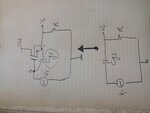
Well I want to use a MOSFET in a RC circuit instead of a capacitor, the MOSFET itself being the capacitor itself should give an input signal, the model I used for the Gate Source Capacitor is in common-DRAIN and you can look at its shape.20191208_150534.jpg
 

The common-DRAIN transistor has a no phase difference between input and input.
You originally asked about MOSFET acting as capacitor, now you switched to common drain amplifier. It's time to clarify the topic and show a schematic of what you are trying to achieve.

- - - Updated - - -

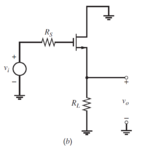
Your RC circuit on the right is a high pass, the common drain amplifier isn't due to the MOSFET transconductance which generates a low output impedance.

Please review the equivalent circuit of common drain amplifier in circuit design text books. See e.g. example from Grey, Hurst, Lewis, Meyer, Analysis and Design of Analog Integrated Circuits.

source follower schematic.PNG

source follower.PNG
 

So how can I make a capacitor with the MOS transistor? What should I connect to the transistor mounts to act as a capacitor for phase difference?What should it be bias and where should region it work?
So far I think if we connect MOSFET anyway, it will become a capacitor

- - - Updated - - -

How does a Mosset become a capacitor in general?
 

How does a Mosset become a capacitor in general?

Do you want a circuit using a MOSFET that does simulate a capacitor? What is the frequency range and the voltage specification?

I presume there are plenty of active capacitor circuits on the internet. But you may miss some of the features.
 

Yes, exactly, the sine input signal with the frequency range of 20 Hz to 20 KHz
plz help me
 

Status
Not open for further replies.

Similar threads

Part and Inventory Search

Welcome to EDABoard.com

Sponsor

Back
Top