Continue to Site

Welcome to EDAboard.com

Welcome to our site! EDAboard.com is an international Electronics Discussion Forum focused on EDA software, circuits, schematics, books, theory, papers, asic, pld, 8051, DSP, Network, RF, Analog Design, PCB, Service Manuals... and a whole lot more! To participate you need to register. Registration is free. Click here to register now.

Connect MQ135 Gas Sensor to Raspberry Pi 3B+

Status
Not open for further replies.

cloner

Newbie level 3
Joined
Dec 5, 2019
Messages
4
Helped
0
Reputation
0
Reaction score
0
Trophy points
1
Activity points
50
Hello experts!

I am totally new to electronics and I need help with connecting the MQ135 Gas sensor with my raspberry pi 3B+ and with interpreting the data that the sensor provides. My main problem is that the sensor provides analog signals and the RPi 3B+ does not have a pin for analog signals.

Therefore I bought an ADC (ADS1115) with 16bit precision. I followed the following guide to read the data from the ADS1115 via python libraries on the RPi:

https://learn.adafruit.com/raspberry-pi-analog-to-digital-converters/ads1015-slash-ads1115

This way I can monitor the provided values from the analog inputs (AIN0 - AIN4). I do not understand what I am actually reading. The values fluctuate and with the GAIN parameter in the python script set to1 I get values in the range of 3000-5000 (but nothing is connected to the analog inputs of the ADC - so why do I see values at all?).

When I connect the AOUT pin of the MQ135 with AIN0 of the ADC the values from every analog input (AIN0 - AIN4) change - shouldn't only the value from AIN0 change?

The breadboard looks like this:
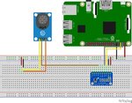
breadboard.jpg

In the scheme it says that it is the MQ9 - but I am using MQ135. The brown cable connects the analog out pin of the MQ135 with the AIN0 of the ADS1115.
The yellow calbe of the MQ135 is VCC and the orange cable is GND.

My questions:

1. Should I change something on the breadboard?
2. How should I interpret the data that the ADS1115 is providing?
3. Why is the ADS1115 reading signals when nothing is connected to AIN0 - AIN4?

I would also be very thankful if someone could maybe show me some sources which would help me to make further research.

Thank you!
 

Values read for unconnected (floating) ADC inputs are meaningless. You can either connect known DC voltage for test or just ignore these values. Check the values for ADC0 input connected to sensor.
 

Check the values for ADC0 input connected to sensor.

I connected the ADC0 input with the 5v pin of the pi but the value is extremely fluctuating. It does not seem to provide usable values. ?
Do you know what the problem might be?
 

I connected the MQ135 to the AIN0 of the ADC and the value is fluctuating extremely. Do you know why this could be?
 

Hi,

I connected the ADC0 input with the 5v pin of the pi
are you sure 5V is within the specified ADC input range?
What output value do you expect with this configuration.
What range of ouput values do you see?

****
Generally: No input (independent of used or not) should be left floating.
Be sure to have valid levels on all ADC inputs and the ADDR pin.

I connected the MQ135 to the AIN0 of the ADC and the value is fluctuating extremely.
I tried to input "extremely" into my caclulator, but it shows an error. ;-)

What does "extremely" mean? --> give values.

Do you know why this could be?
* wrong/bad wiring
* noise pickup in wiring
* fluctuating VCC
* fluctuating ADC_VREF
* ground bounce
* wrong software

I allways recommend to put an RC lowpass between signal_source and ADC. The C connected as close as possible to ADC_input and A_GND.

Klaus
 

are you sure 5V is within the specified ADC input range?

Yes, the data sheet of the ADC mentions that the Supply Range is 2.0V up to 5.5V

What output value do you expect with this configuration.
What range of ouput values do you see?

I do not really know what to expect. After some research I found out that gas sensors have to be calibrated with chemical samples and an adjustable resistor. Nevertheless the fluctuations I see seem strange to me.
****
Be sure to have valid levels on all ADC inputs and the ADDR pin.
ADDR is not connected at all. The beginners tutorial did not consider this pin. - So I did not either.

In the data sheet stands that a 0.1mF Capacitor should be placed between VDD of the ADC and the power source. Could this maybe be an issue?

I tried to input "extremely" into my caclulator, but it shows an error. ;-)
What does "extremely" mean? --> give values.

The value Range from 0 to 14000 - I cannot interpretate these values. The value increases sometimes up to 14000 and then falling again to 0 without me doing anything or without changes in the air of the room.

I allways recommend to put an RC lowpass between signal_source and ADC. The C connected as close as possible to ADC_input and A_GND.

Are you talking about pull-up/pull-down resistors?
 

Hi,

Yes, the data sheet of the ADC mentions that the Supply Range is 2.0V up to 5.5V
My question was not about supply range. It was about input range.

I do not really know what to expect. After some research I found out that gas sensors have to be calibrated with chemical samples and an adjustable resistor. Nevertheless the fluctuations I see seem strange to me.
My question was for "in this configuration" ... and I referred to your: " connected the ADC0 input with the 5v pin of the pi "

In the data sheet stands that a 0.1mF Capacitor
Sure? 0.1mF = 100uF

The value Range from 0 to 14000 - I cannot interpretate these values. The value increases sometimes up to 14000 and then falling again to 0 without me doing anything or without changes in the air of the room.
Either your software is wrong or you measure a floating input.

Are you talking about pull-up/pull-down resistors?
No.
R = resistor, C = capacitor.
Read about RC low pass filter.

Klaus
 

Keep in mind that the 5v available at the PI connector header is not intended to supply external devices, but rather to use with external pullup resistors or any other circuits that do not demand too much current. Note that their were routed on the Raspberry board with thin tracks. Considering that you also have to feed the RPI with the same 5v, why don't just bypass it and take the 5v straight from the power supply? Regarding the capacitor, yes, it's always welcome, but for you, a ceramic in addition with the electrolitic would help.
 

Status
Not open for further replies.

Part and Inventory Search

Welcome to EDABoard.com

Sponsor

Back
Top