Continue to Site

Welcome to EDAboard.com

Welcome to our site! EDAboard.com is an international Electronics Discussion Forum focused on EDA software, circuits, schematics, books, theory, papers, asic, pld, 8051, DSP, Network, RF, Analog Design, PCB, Service Manuals... and a whole lot more! To participate you need to register. Registration is free. Click here to register now.

RC LPF Filter Circuit

Status
Not open for further replies.

timjohnson

Newbie level 3
Joined
Mar 2, 2019
Messages
4
Helped
0
Reputation
0
Reaction score
0
Trophy points
1
Activity points
47
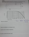
Hello, I'm a beginner in electronics, sorry if what I'm asking is basic. I have a task for one of my assignments which I'm unsure about. It is about RC LPF filters. I am asked to modify a circuit so the cut-off frequency is doubled. How would I go about doing so? Would I simply reduce the resistor or capacitor value for the formula: F(cutoff)= 1/2piRC. Also how would I show this practically? My lecturer says to keep the amplitude of the input constant but I'm not sure what he means by that. The circuit consists of just a signal generator, supplying a resistor of 1k and capacitor of 100n and a Vout measurement between the resistor and capacitor. Any help would be great. I have also attached an image.
 

Attachments

  • 20190228_095959.jpg
    20190228_095959.jpg
    443.4 KB · Views: 140

Hi,

Would I simply reduce the resistor or capacitor value for the formula: F(cutoff)= 1/2piRC.
Yes. Which one, or both... you could do as you like unless there are other requirements.

Also how would I show this practically?
Maybe just use another 1k resistor and connect it in parallel to the existing one.

My lecturer says to keep the amplitude of the input constant but I'm not sure what he means by that.
I don´t know either: --> so ask him.

and a Vout measurement between the resistor and capacitor.
I dont like this phrase. Maybe I´m a bit pedantic.
V_out is a single node: this is what you mean "between resistor and capacitor"
But a "measurement" needs two points. in your case: V_out and GND. You could say "V_out measurement is across the capacitor"

Klaus
 

lecturer says to keep the amplitude of the input constant but I'm not sure what he means by that.

It could mean:
(a) use the same amplitude from the signal generator as from the first frequency sweep,

or it could mean:
(b) your second plot shall result in 0dB drop at the low end of the frequency sweep, similar to the first sweep.

As for which components to modify, you are correct to observe (in the formula) that changing either R or C or both will alter the rolloff frequency. I suppose the exercise is asking for the easy and simple change you can make, so the rolloff frequency is doubled.
 

But a "measurement" needs two points. in your case: V_out and GND. You could say "V_out measurement is across the capacitor"

Klaus

I see what you mean by this. thank you.

I forgot to mention that the signal generator has an output impedance of 600 ohms, how would this effect the circuit?

Also I kept V_in the same amplitude (1v), but when I change frequencies from 100ohm to 1kohm the amplitude drops and is not constant. Shouldn't it be the same, as those frequencies are before the roll off?
 

In regard to the task (just to check on progress), did you figure out the answer to the original question?

signal generator has an output impedance of 600 ohms, how would this effect the circuit?

I guess you're talking about tests with a real signal generator? 600 ohms creates a large enough change that it affects the cutoff frequency. If it stays at 600 ohms through the sweep then you can add it to the 1k in the schematic.

Also I kept V_in the same amplitude (1v), but when I change frequencies from 100ohm to 1kohm the amplitude drops and is not constant. Shouldn't it be the same, as those frequencies are before the roll off?

Do you mean to say 100 Hz to 1k Hz? If you're measuring with an inexpensive meter, then this is typical since they are usually calibrated to measure house voltage at 50 or 60 Hz. However a different frequency throws off the readings.

If you're measuring the signal generator's raw output with an oscilloscope then the signal generator is not acting right. You can still run the sweeps although you need to compare the source voltage and filter voltage, and do so at several frequencies to generate a frequency response graph.

The signal generator is supposed to produce a flat frequency response at an unchanging output impedance.
 

In regard to the task (just to check on progress), did you figure out the answer to the original question?
Yes, so I understand now that to double the cut off frequency you could either change the value of the resistor or capacitor or even both. It does not specify which one so I just went with the resistor.


I guess you're talking about tests with a real signal generator? 600 ohms creates a large enough change that it affects the cutoff frequency. If it stays at 600 ohms through the sweep then you can add it to the 1k in the schematic.
That's correct, I'm testing out the circuit with a real audio generator, which has an output of 600ohms. I remember being told to keep V_in amplitude constant, and consider the 600ohm input impedance. I suppose that's where I got confused and can't make sense out of it.


Do you mean to say 100 Hz to 1k Hz? If you're measuring with an inexpensive meter, then this is typical since they are usually calibrated to measure house voltage at 50 or 60 Hz. However a different frequency throws off the readings.
Apologies, I meant 100 Hz to 1k Hz
 

I'm testing out the circuit with a real audio generator, which has an output of 600ohms. I remember being told to keep V_in amplitude constant, and consider the 600ohm input impedance.
That means, for each frequency you measure, you adjust the generator output to the same voltage, since the varying filter load will cause the generator output voltage to vary with frequency.
 

Status
Not open for further replies.

Similar threads

Part and Inventory Search

Welcome to EDABoard.com

Sponsor

Back
Top