Continue to Site

Welcome to EDAboard.com

Welcome to our site! EDAboard.com is an international Electronics Discussion Forum focused on EDA software, circuits, schematics, books, theory, papers, asic, pld, 8051, DSP, Network, RF, Analog Design, PCB, Service Manuals... and a whole lot more! To participate you need to register. Registration is free. Click here to register now.

Phase shifted pwm using stm32f103

Status
Not open for further replies.

lordgty

Junior Member level 1
Joined
Jul 7, 2010
Messages
19
Helped
1
Reputation
2
Reaction score
1
Trophy points
1,283
Location
Pakistan
Activity points
1,380
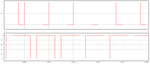
I am trying to build a current fed push pull DC DC converter. This requires two waveforms with duty cycle greater than 50% and phase difference of 180 dergrees. I have attached pic.

I would like to know the possible ways of achieving this. I have tried using output toggle option but that doesn't seem to work. Any suggestions and help will be highly appreciated.​
 

Attachments

  • Untitled.png
    Untitled.png
    13 KB · Views: 277

Since you want two waveforms staggered 180 degrees apart...
It's handy to put in a D flop to divide-by-2. Then install logic gates which rotate the incoming clock signal to two outputs. Duty cycle is identical to all devices and is adjustable at one potentiometer.

In this case 'OR' gates produce a duty cycle longer than 50%. In other situations it might be AND, NAND, NOR, OR, etc. It depends on whether you need to rotate high pulses to devices, or low pulses, or use inverted logic, etc.

D flip-flop and 2 OR gates distrib 2 pulses 51-99 pct.png

- - - Updated - - -

The above displays one strategy and there may be other methods which allow you to use the signal from your controller IC.
 
Thanks for reply.
What I am trying to do is: two triangular waveforms out of phase with each other by 180 degrees are compared by the same duty cycle. I have attached circuit diagram for clarity. This results in two square waves that overlap each other. Kindly see the figures attached and advise me how to generate this using timers in stm32f103.Circuit.pngwaveforms.png
 

Hi,

What I am trying to do is: two triangular waveforms out of phase with each
Now I'm confused.
This sentence clearly says you want two triangular waveforms...--> I assume this is not possible without additional circuitry

From the post#1 I thought you want to generate two square waves.
I'm not familiar with STM32...
But with other microcontrollers.
I see several possible solutions:
1) maybe the PWM hardware is cofigurable for this --> read datasheet
2) use two counters, each used for one PWM. Start one counter, delay the start of the second counter by 50% of the first counter.
The above need no processing power, no ISR.

Now with ISR:
3) run one counter. Run it with twice the expected frequency. On TOP interrupt alternatively SET the PWM outputs. At compare match interrupt alternatively CLEAR the PWM outputs. It needs additional logic when crossing the 50% duty cycle border.

4) use a timer to generate high frequency interrupts. Use two software counters with 50% deviation. Use software compare to set/ clear the port pins.

Klaus
 
Status
Not open for further replies.

Similar threads

Part and Inventory Search

Welcome to EDABoard.com

Sponsor

Back
Top