Continue to Site

Welcome to EDAboard.com

Welcome to our site! EDAboard.com is an international Electronics Discussion Forum focused on EDA software, circuits, schematics, books, theory, papers, asic, pld, 8051, DSP, Network, RF, Analog Design, PCB, Service Manuals... and a whole lot more! To participate you need to register. Registration is free. Click here to register now.

Help in nodal analysis

Status
Not open for further replies.

farah123

Newbie level 3
Joined
May 11, 2018
Messages
3
Helped
0
Reputation
0
Reaction score
0
Trophy points
1
Activity points
25
Dear all

I’m trying to understand chau circuit in chaotic system, one of the proposed CLC circuit with parameters attached bellow showed a final parameters of the circuit. Can anyone help me with the nodal analysis of these parameters? How the researcher derived them?

circuit.png
 
Last edited by a moderator:

The pdf has equations which appear to show ratios between components, but they do not give specific working values. Fortunately I like to play with simulations, and I spent some time experimenting with your Chua oscillator. The goal is to start L & C2 oscillating back and forth at their resonant frequency, while C1 introduces a different frequency.

The two frequencies can be approximately an integer multiple, though not exactly. If it is exact, then they tend to 'lock' into alignment, preventing chaotic behavior. To gain success, components need to be adjusted higher or lower in small steps.

Chaos is in a category where it's hard to apply a formula. I'm fairly certain the author assembled a Chua circuit (hardware or simulated), then played with values until oscillations neither died away, nor continued at a fixed frequency, but wandered between regular and random.

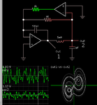
Here is my simulation after I finally got it working.

Chua chaotic oscillator 2 opamps w lissajous May2018.png
 

thanks for your quick reply.You have done very great job.But I was wondering about the parameters A,B and C. Can you kindly show me how to derive them?bellow some details about the circuit ...
looking forward to you help.

A3.png
 

wondering about the parameters A,B and C. Can you kindly show me how to derive them?

Seeing how the equations are printed, it makes me wonder how important the author regards them? The variables run together in a row. I have trouble distinguishing each variable, because some have a subscript, and subscripts ought to be small rather than printed full size.

I guess what I'm saying is that the author seems to give brief mention of parameters A, B, C. I have a hunch they have something to do with ratios of frequencies, or ratios of component values. It's as though their equations are distilled from a combination of the standard formulae for LC resonance and RC time constants and L/R time constants. I do not believe parameters A, B, C were the first steps toward creating the circuit. I think the author first got the oscillator working successfully, then derived a dozen equations from those component values. One or several of those equations may be associated with success. After all these are not the only component values which work in this circuit. Furthermore there are other Chua circuit topologies, which do not necessarily make use of parameters A, B, C.


dear sir
I really appreciate your time and effort you spent on my thread. I attached the complete paper and the mentioned circuit is on page 733 . it will be very kind of you if you could guide me to derive them because Im totally lost with this sticky problem.thanks again for your reply.
 

Seeing the complete article, I'd say it is written for college level math. It uses words like eigenvalue and Jacobian and Lyapunov. (Words that are over my head.) Some passages talk about how the circuit operates. Other passages talk about the math of chaotic motion.

The article refers to parameters A, B, C as 'functions of passive components.' These components are the resistors, capacitors and inductor. The original raw equations are in the text. They're in a complicated form. They contain a lot of combinations of R & C & L, and their reciprocals. Several terms have a line through them, indicating that they cancel due to identical combinations above and below the divisor line. Eventually the equations are reduced to a form containing just a few terms.
er
If you ask me the simpler form does not make it any easier to understand how the chaotic circuit behaves. In fact the article states that "parameters A & B can be treated as constants." Parameter C implies that circuit behavior is based on the resonant frequency created by inductor L1 & C2, and a competing frequency acting through R & C1.

I say this because the formula for LC resonance is:

F= 1 / (2 Pi sqrt(LC))

and the rolloff frequency for RC is:

F= 1 / (2 Pi RC)

The competing waveforms do not add together. They interfere with each other, creating a third waveform. The third waveform is chaotic, making it difficult to identify either of the first two waveforms.

- - - Updated - - -

To get a grasp on the circuit action, I was helped greatly by watching it in the animated simulator programmed by Paul Falstad. The schematic is the screenshot in my post #2 above.

Free to download and use:

www.falstad.com/circuit

The simulator portrays current bundles moving through wires, back and forth. It makes it very easy to observe resonant action in L & C2, and interfering frequency from C1.
 

Status
Not open for further replies.

Similar threads

Part and Inventory Search

Welcome to EDABoard.com

Sponsor

Back
Top