Continue to Site

Welcome to EDAboard.com

Welcome to our site! EDAboard.com is an international Electronics Discussion Forum focused on EDA software, circuits, schematics, books, theory, papers, asic, pld, 8051, DSP, Network, RF, Analog Design, PCB, Service Manuals... and a whole lot more! To participate you need to register. Registration is free. Click here to register now.

3-Band Graphic Equalizer

Status
Not open for further replies.

devonsc

Advanced Member level 4
Joined
Nov 30, 2004
Messages
115
Helped
2
Reputation
4
Reaction score
1
Trophy points
1,298
Activity points
1,931
3 band eq schematic

Hi there,

I'm new in equalizers, very new in fact. At this moment, I'm trying to search for a 3-band Graphic Equalizer circuit for analysis. Any advice? or websites to recommend?

I tried searching and it seems that I only found 5-band equalizer. Does it mean that it simply goes in this manner? => 5 band means 5 op-amp used, whereas 3-band means 3 op-amp used? :) Sorry if I'm really talking nonsense here.

Hope no one will get mad. Help needed. Thanks in advance. Bye.
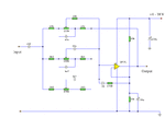
 

3 band graphic equalizer

It could be made as 3 opamp with the frequency band adjusted to it. Normally when three is required you already have two of it that is Bass and Treble then what is required is midband filter which you will find as Precense control. That is why when a GEq is required one goes for a minimum of 5
 

parametric equalizer schematic

Equalizers can be made as decade, tercet, octave etc. Each regulator has it's own frequency at which it boosts or attenuates the signal. It is usually realized as series resonance circuit with active inductor and gain regulation. All stages of equalizer follow the same concept, only frequency determining elements changes.
For study purposes it does not matter if you take 3 or more bands as an example.
 

3 band equalizer schematic

hi,
u can find useful data at
**broken link removed**
 

graphic equalizer schematic

There is another form of equalizer where you can control the center frequency, bandwidth, and gain. I think that this is called a parametric equalizer. It is used for mitigating the resonance effects of a large room.
 

parametric eq schematic

See Attachment please ! Very basic equalizer schematic...

Description :

Using a single op-amp this easy to make equalizer offers three ranges, low frequency,mid frequency,and high. With component values shown there is approximately +/-20dB of boost or cut at frequencies of 50Hz, 1kHz and 10kHz. Supply voltage may be anything from 6 to 30 Volts. Maximum boost 20dB is only realized with maximum supply voltage.
 

Attachments

  • 3_band_equalizer_184.gif
    3_band_equalizer_184.gif
    7.7 KB · Views: 108

3-band eq schematic

Thanks a lot, will study the circuit thoroughly. But would like to ask about: This thought I have in mind all the while.

3-band requires 3 op-amp
5-band requires 5 op-amp
and so on, as in one band requires one op amp.

So, this is totally nonsense? :( Sorry, hope you dont mind to comment about this.
 

3 band graphic equalizer circuit

Two shelving (Bass and Treble) and one presence (1K) can be implemented using 1 op-amp.

For most advanced IC's in audio, check AD1940 and TAS3002.

bimbla.
 

graphic equalizer frequencies

Above circuit is a simple tone control with separate bass, treble and mid tone controls. Graphic equalizers are something like this circuit: **broken link removed**
 

3 band equalizer schematics

i have the same problem
 

graphic equalizer circuit

well there is a software that might helps you,

you must design your filters and then add the resulting signals in a adder op amp

**broken link removed**
 
Status
Not open for further replies.

Part and Inventory Search

Welcome to EDABoard.com

Sponsor

Back
Top