Jetstream
Newbie level 4
Hi Guys,
I need to sense DC current of a 300vdc power rail. The amps to be sensed are in the range of 0-10A.
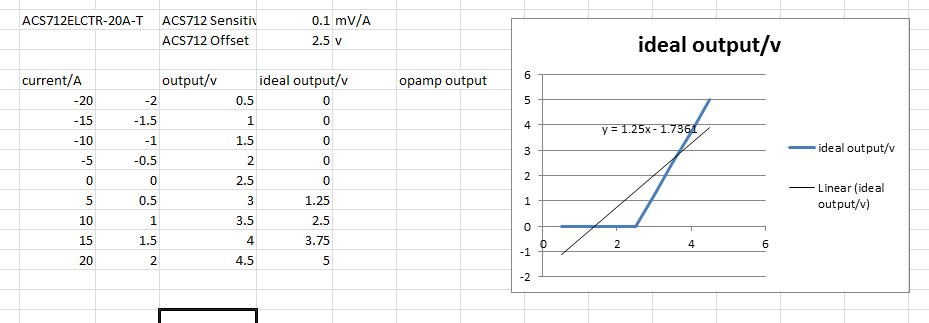
I currently have a ACS712ELCTR-20A-T hooked up to a PIC and can measure the output no problem. At 0amps I can read 2.5v at the adc and the voltage swings as the current changes, no problem there.
The problem I have is that I'm stuck with the ACS712 due to availability/logisitics etc...
and I want to make better use of the PIC's ADC by doing the following:
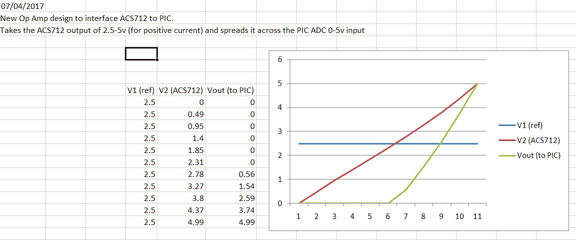
1) Instead of 2.5v (adc) = 0 amps, I want 0v (adc) = 0 amps.
2) I also want to stretch the range of the ACS712 so that 0v (adc) = 0 amps and 5v (adc) = 15 amps.
I want to do this using only a +5vdc supply, not a +/- bipolar supply.
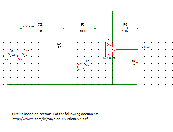
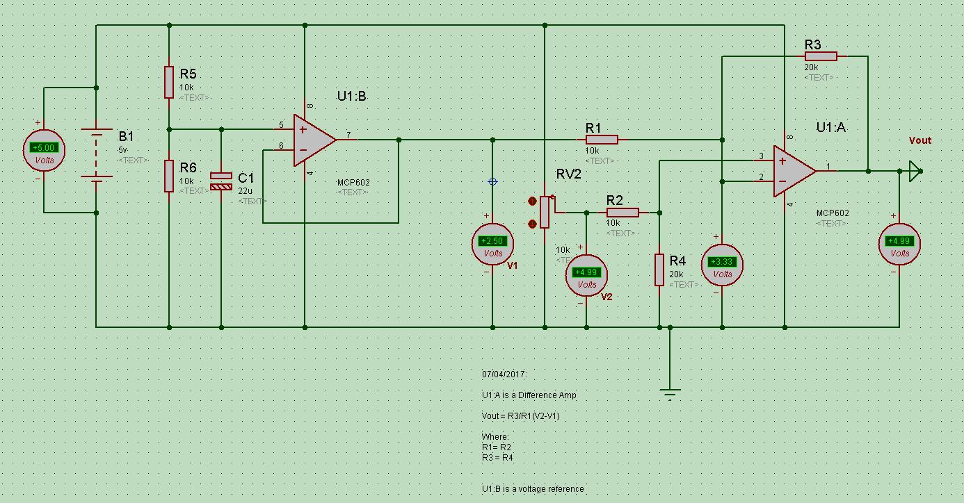
I was thinking that an opamp circuit using a MCP602 might do the trick in a scale and offset type circuit, but I can't get it to work right.
Any ideas on how to implement this function?
Regards,
JetStream
I need to sense DC current of a 300vdc power rail. The amps to be sensed are in the range of 0-10A.
I currently have a ACS712ELCTR-20A-T hooked up to a PIC and can measure the output no problem. At 0amps I can read 2.5v at the adc and the voltage swings as the current changes, no problem there.
The problem I have is that I'm stuck with the ACS712 due to availability/logisitics etc...
and I want to make better use of the PIC's ADC by doing the following:
1) Instead of 2.5v (adc) = 0 amps, I want 0v (adc) = 0 amps.
2) I also want to stretch the range of the ACS712 so that 0v (adc) = 0 amps and 5v (adc) = 15 amps.
I want to do this using only a +5vdc supply, not a +/- bipolar supply.
I was thinking that an opamp circuit using a MCP602 might do the trick in a scale and offset type circuit, but I can't get it to work right.
Any ideas on how to implement this function?
Regards,
JetStream