Akshaydpal
Member level 1
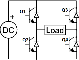
For +ve half cycle Q1 =PWM1 Q4= ON Q2=Q3=OFF
For -ve half cycle Q3= PWM2 Q2 =ON Q1=Q4=OFF
PWM1 is 180 out of phase with PWM2
generated from Pic micro controller
in the above sequence high side MOSFET are given PWM and Low side are just turned ON and OFF as required
is IT POSSIBLE TO INVERT this sequence means
for +ve half cycle Q1 =ONQ4= PWM1 Q2=Q3=OFF
For -ve half cycle Q3= ONQ2 =PWM2 Q1=Q4=OFF
will there be any complications or it will just work fine practically ??