Continue to Site

Welcome to EDAboard.com

Welcome to our site! EDAboard.com is an international Electronics Discussion Forum focused on EDA software, circuits, schematics, books, theory, papers, asic, pld, 8051, DSP, Network, RF, Analog Design, PCB, Service Manuals... and a whole lot more! To participate you need to register. Registration is free. Click here to register now.

Optocoupler as current sensor

Status
Not open for further replies.

Anical

Newbie level 6
Joined
Jun 29, 2015
Messages
13
Helped
0
Reputation
0
Reaction score
0
Trophy points
1
Activity points
133
Hi.
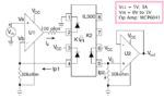
I am using IL300 optocoupler for my voltage isolation (except 1 output voltage value rest all linear to the input). I want to use the same for current sensing and connect it to my ADC. I am not sure if for the current sensing its the same circuit as mentioned in the datasheet under typical application circuit or its different.
The current range I want to measure is from 1 amps to 2 amps.
I am using a voltage divider circuit for my voltage sensor configuration and I believe it should be the same for my current sensing circuit.
my load is 185 ohms and my power resistor (across which I am measuring the voltage) is 1 ohms with 25W.

I am not sure if this will help or not, my microcontroller is PIC18F4550 and I am using external oscillator.
 

Hi,

Show your schematic.
Do you want to operate the optocoupler in linear (analog mode) or switching (digital, saturating) mode?

Klaus
 

The IL300 can take 0.5 to 40 mA and you need to scale your current using a shunt. But once you are using the power resistor, you have essentially converted the current into voltage. You can use this voltage to drive the example circuit mentioned in the datasheet.

Can you please be more clear in what exactly IS the question?
 

Can you please be more clear in what exactly IS the question?

My question is what configuration I should use with my IL300 to use it as a current sensor.

You mentioned that I should scale the current using a shunt since the input amps range for coupler is quite low, should I be using a variable resistor?
How should I select that shunt value?

- - - Updated - - -

Show your schematic.
Klaus

Did you mean the current sensor or the voltage sensor?


Do you want to operate the optocoupler in linear (analog mode) or switching (digital, saturating) mode?

Klaus
In Linear (analog mode)
 

Attachments

  • voltage sensor.PNG
    voltage sensor.PNG
    26.5 KB · Views: 207

Hi,

I still don't see the problem.

In your given circuit ... Vin is the voltage coming from the current sensing shunt..
Use the circuit as it is.

Then tell us:
What testing values did you use?
What do you expect?
And what does happen instead?

Klaus
 

In Linear (analog mode)

The circuit presented produces an output proportional to the input voltage; yes, the input voltage can come from a shunt resistor.
 

To reduce power dissipation, the shunt resistor is usually *very low* valued, producing a very low drop...perhaps 100 mV at full scale.
Thus, you require a front end opamp, to amplify that voltage to, let's say, 5 volts full scale.

Because the low input voltages involved, the front end opamp must have a low offset voltage. I would say below 1/2 millivolt to have 0.5% error.
 

Thus, you require a front end opamp, to amplify that voltage to, let's say, 5 volts full scale.
In a low part count design, this low offset OP can directly drive IL300, just change the current feedback resistor for respectively lower input voltage range.
 

Hi,

I still don't see the problem.

In your given circuit ... Vin is the voltage coming from the current sensing shunt..
Use the circuit as it is.

Then tell us:
What testing values did you use?
What do you expect?
And what does happen instead?

Klaus

I actually misunderstood the concept. The resistor that will be added at Vin will convert current to voltage. I did not pick up this and hence throughout I thought it was a voltage sensor and NOT a current sensor. Finally I realized it.

- - - Updated - - -

(I took a break from working on this so I apologies for such a delay response that almost made this thread seem dropped)

The above circuit works well if the signal is unipolar however if the signal is bipolar the circuit configuration changes. I am trying to use the above isolation technique to my advantage and isolate high current (~8A) from the ADC which will calculate the current flowing through the resistor. I am using shunt resistance way. In this case the shunt will not be grounded so I am trying to come up with a design to make it work. Till now I am able to achieve an op amp config. for sensing the current in high side however I have not been able to successfully use IL300 to isolate the output to my ADC input.

Are there any suggestions?

[EDIT]
The op amp configuration is:
Capture.PNG
I have set RIN = R*=30k ohms
 
Last edited:

Status
Not open for further replies.

Similar threads

Part and Inventory Search

Welcome to EDABoard.com

Sponsor

Back
Top