Continue to Site

Welcome to EDAboard.com

Welcome to our site! EDAboard.com is an international Electronics Discussion Forum focused on EDA software, circuits, schematics, books, theory, papers, asic, pld, 8051, DSP, Network, RF, Analog Design, PCB, Service Manuals... and a whole lot more! To participate you need to register. Registration is free. Click here to register now.

555 charge pump - negative voltage too low

Status
Not open for further replies.

boylesg

Advanced Member level 4
Joined
Jul 15, 2012
Messages
1,023
Helped
5
Reputation
10
Reaction score
6
Trophy points
1,318
Location
Epping, Victoria, Australia
Activity points
11,697
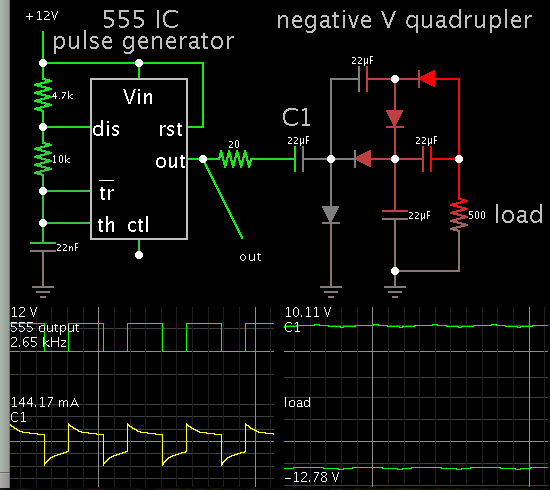
With respect to this circuit:

NegativeVoltage.gif


With a 12V supply I am only getting about -7V out of it with a CMOS 555.

Does anyone have any suggestions on how I could get it closer to -12V?
 

Hi,

use a true voltage converter IC, like ICL7662 or similar.

Klaus
 

You can use schottky diodes to make the drop-loss over each diode less. Check your load current. The 555 can only provide about 100 mA of peak output current to charge the caps. You can also increase the frequency ( 1/2 your timing cap value) to have energy transfers more often to your load.
 

Add stages to make a negative voltage quadrupler.


The 20 ohm resistor is unnecessary. It's a simulated way to reduce output from the 555 IC to a realistic level.

- - - Updated - - -

It is called a quadrupler because it has 4 diode-capacitor stages. If true AC were applied then output voltage would be much higher. However since we are applying pulsed DC only, the output amplitude is less.
 

At worst, the C555 can have a high output of only 10.5 V @ 10 mA when operated from a 12 V supply. This will decrease with increased output current.

Apart from increasing the operating frequency, you can boost the current and ensure switching very close to the rails. The circuit below can do that for you.

Although at this stage, it may be better to use the chip suggested by Klaus if you don't need the added current drive capability.
 

Attachments

  • 555_boost_-ve.png
    555_boost_-ve.png
    66.5 KB · Views: 341
Check your load current. The 555 can only provide about 100 mA of peak output current to charge the caps.
It is not a powerful ordinary 555. Instead it is a weak Cmos one. The datasheet for the ICM7555 shows an output loss of 1V when its peak output sourcing current is only about 3.5mA with a 12V supply.
 

The LCM555 from TI shows maximum sink and source currents of 100 mA. They don't give the saturation levels at this current. It is already bad with the 50 mA figure they provide, so at 100 mA it will be terrible.
 

I agree that a half-bridge can be added (per E-design's post #5) in order to boost current output, if insufficient current is available from the 555 IC to drive my voltage multiplier (post #4).
 

For some reason a complementary pair just did not occur to me so thanks for that. It gets me to -10 to -11V and that is probably as far as I am likely to get short of using an ATX power supply with it +12 and -12V.
 

Will the circuit using the complimentary pair use a Cmos or an ordinary 555? How much current from -11V do you need?
 

Hello I don't create new thread, i reply in this thread.
I create this negative voltage generator with 5V i have -4.0V voltage output, but when I add load voltage falls to -1.5V i need only 10mA even when i placed 100K load voltage falls
 

At 5 V the best you will do will be about -4.4 V, even with using the low drop schottky diodes.
 

Attachments

  • 555_boost_-ve.png
    555_boost_-ve.png
    39.2 KB · Views: 164

Hi,

* Next time please start your own thread
* show exactely YOUR schematic, with all voltages, part values and exact part names
* read post #2

Klaus
 

Status
Not open for further replies.

Part and Inventory Search

Welcome to EDABoard.com

Sponsor

Back
Top