Continue to Site

Welcome to EDAboard.com

Welcome to our site! EDAboard.com is an international Electronics Discussion Forum focused on EDA software, circuits, schematics, books, theory, papers, asic, pld, 8051, DSP, Network, RF, Analog Design, PCB, Service Manuals... and a whole lot more! To participate you need to register. Registration is free. Click here to register now.

How to evaluate the on-chip IR drop&Ldi/dt's effect on noise?

Status
Not open for further replies.

xiangx93

Newbie level 6
Joined
Jan 4, 2017
Messages
11
Helped
0
Reputation
0
Reaction score
0
Trophy points
1
Activity points
117
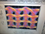
I've recently designed a wireline transmitter,but it turns out to have so much jitter.Since I can make sure that the clock generator is relatively clean,I think the noise most probably comes from some on-chip mechanism like IR-drop or inductor-induced jitter.So is there any way to approximate the IR&inductor's influence on circuits' performance?(Preferrably in Cadence) 24Gbps.jpg
 

Yes, you can do this, it needs you to derive / extract
the LRCM mesh accurately and impose likely aggressors
and so on. I've been able to make DJ appear in Spectre
analog_extracted based simulations, C-only, from long
lines routed in proximity. I have no idea whether your
tools and PDK support inductance (let alone mutual).

But the 'scope looks very random, not determinstic
although the behavior of the top band suggests a
power integrity problem to me. And this could be
external or internal. I think you're in a hurry to get
to the on-chip verdict and should spend some more
time at the pins, looking for things that seem to
have a similar "heartbeat" to some of the signal
jitter (as it appears that some of it shows on the
'scope).

From the picture it also appears that the signal
is very "decimated" / pixellated, as if there was a
too-sparse sampling going on instead of a more
continuous acquire. That could hide useful clues.
 

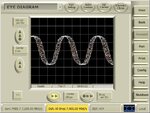
The picture above shows PRBS7 pattern at 24Gbps,while this one indicates the clock working at 7GHz3#1.4_1.6_1000_7g.jpg
 

What I see is, your clock*measurement rollup has
about 20pS of jitter, and the 4-level data waveform
is showing about 60pS. So you might say that there
is 40pS of "contributed jitter".

With prime (incoming) jitter 1/3 of the total, there
has to be some questions about test hardware setup.
Me last time at that rodeo was a decade back, and
it took us working on an optical bench, a whole lot
of copper braid and solder and decoupling caps, and
the best 'scope the company had (and cables to
match the spendiness) to get down to a repeatable
15pS-range contributed jitter.

You might step back a bit, try to see what the clock
looks like when you acquire it on one channel and
trigger from another on the same sampling basis as
the eye mode you showed. Have to get that clean
before you can chase anything more mysterious.
I think you'd benefit by quantifying the various
components of the displayed jitter - source phase
noise, trigger repeatability, common mode bounce
and edge-rate vs trigger level, channel BW impacts,
etc. Any of these might "bury" or "smear" the kind
of deterministic jitter that you'd expect a chip
interconnect type problem, to add to the mix. And
you can set proper expectations for the casual
reviewer, who might freak out over 60pS jitter on
this bench lashup (?) if you didn't tell them that
30pS of it (say) was imposed by the equipment
and external hardware.

Then I'd set up an "eye diagram" where you capture
the clock while triggering from the data (a level of
your choosing, try several) and see how that compares
to the "canned" eye diagram. You'd hope they give the
same answer, but hope != trust. Look for ways you
can cross-check the instruments and methods.
 

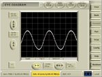
Since I have used the same clock generator to trigger another TX,which shows little overall jitter,I believe the jitter mostly doesn't come from the test setup itself,so I can focus more on some on-chip factors like IR Drop or Ldi/dt Noise.
The pic in #3 shows the TX output when data input is static so that the waveforms can reflect the clock which triggers the data.The pic below indicates the same thing,with the only difference that this TX produces little jitter.

6#1.25_1.5_1000_8g.jpg
 

Status
Not open for further replies.

Part and Inventory Search

Welcome to EDABoard.com

Sponsor

Back
Top