Continue to Site

Welcome to EDAboard.com

Welcome to our site! EDAboard.com is an international Electronics Discussion Forum focused on EDA software, circuits, schematics, books, theory, papers, asic, pld, 8051, DSP, Network, RF, Analog Design, PCB, Service Manuals... and a whole lot more! To participate you need to register. Registration is free. Click here to register now.

3 phase control circuit

Status
Not open for further replies.

electronicsIUST

Member level 3
Joined
Feb 12, 2017
Messages
67
Helped
0
Reputation
0
Reaction score
0
Trophy points
6
Activity points
575
Hi, I found below circuit for controlling three phase system and detecting faults like over/under voltage and phase unbalance. But I can't understand some parts. Can anyone help me to analyze this circuit please? Its inputs are 3 phases L1, L2, L3 and control is done by micro controller that in the case of an error activate relay and LEDs.
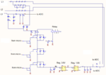
8.png
 

The schematic appears to be incomplete. And is terribly drawn.
 

Once, I made a higschool project on controlling 3 phase induction motors and I used mc3phac ic from freescale. It is very easy to control motors with that ic if you have a proper ipm. The reference design is in datasheet. But I don't know if that chip is still in production
 

Status
Not open for further replies.

Similar threads

Part and Inventory Search

Welcome to EDABoard.com

Sponsor

Back
Top