Continue to Site

Welcome to EDAboard.com

Welcome to our site! EDAboard.com is an international Electronics Discussion Forum focused on EDA software, circuits, schematics, books, theory, papers, asic, pld, 8051, DSP, Network, RF, Analog Design, PCB, Service Manuals... and a whole lot more! To participate you need to register. Registration is free. Click here to register now.

Flyback diode, where extra voltage goes ?

Status
Not open for further replies.

xmen_xwk

Full Member level 3
Joined
Sep 12, 2014
Messages
172
Helped
2
Reputation
4
Reaction score
2
Trophy points
18
Activity points
1,373
I know what flyback diode does, but how it does and where the extra current goes is kind of confusing.

I have an inductive load to switch from both high and low side. So for this, first I try to switch it at low side. Everyone suggests that a flyback diode parallel to load is good to avoid burning up the switch(mosfet). And it does the job.

But where does the extra voltage go ? In some websites I read the current keep circulate the load until all the current is completely dissipate as heat. If thats true, why current is flowing ? there is no ground. And why it doesn't do that when switch is off in first place ?

In one website, long ago I read, the extra voltage goes back to Power supply. Well in that case, that would destroy the psu ?

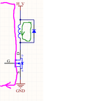
inducitive load.png
 

Hi,

freewh1.PNG

When switch is ON then the current flow is like the left pink line.

When switch is OFF, then current flow is like right green line.... until all the energy stored in the coil is dissipated as heat. Then there is zero current flow.

Klaus
 
There is a simplified expression that the current through the inductance cannot be changed instantly. So when you close the transistor (switch or anything else), the current continues to flow through the inductance causing the reversed voltage drop (according to normal current flow). The voltage drop may exceed several kV that results is sparks (in fact that is the "closing" of current loop) and damages. If you have a diode across the inductance, then after switching off the transistor, the voltage at the lower pin of the inductance becomes greater than at the upper pin and the diode becomes forward-biased and current safely flows using green path on the picture above.
 

If thats true, why current is flowing ? there is no ground.
You do not need a ground for a circuit to work. Ground is just a reference for a known potential that you refer to, in order to know other potentials in other nodes.
If there is no ground (= reference) in a circuit, one can only get to know the difference in electric potential on the different circuit elements but not the electric potential in a specific node.
 

Status
Not open for further replies.

Similar threads

Part and Inventory Search

Welcome to EDABoard.com

Sponsor

Back
Top