Continue to Site

Welcome to EDAboard.com

Welcome to our site! EDAboard.com is an international Electronics Discussion Forum focused on EDA software, circuits, schematics, books, theory, papers, asic, pld, 8051, DSP, Network, RF, Analog Design, PCB, Service Manuals... and a whole lot more! To participate you need to register. Registration is free. Click here to register now.

High frequency trnasformer as galvanic isolation

Status
Not open for further replies.

hanshanshans

Newbie level 4
Joined
Mar 7, 2017
Messages
5
Helped
0
Reputation
0
Reaction score
0
Trophy points
1
Activity points
50
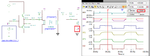
HI, i am designing a ciruit and need galvanic isolation for a high frequncy AC signal, preferebly form around 700kHz to about 1.2MHz. I have simulated the circuit using 1:1 transformers with very nice result, but i am having truble finding suitable transformers in real life. The problem i am trying to solve, is sending a 60mA AC signal on to a 24V DC line.
Anyone have any tips as to where i can search to find transistors that might fit in my circuit?
 

Hi,

**broken link removed**

Klaus
 

[merged]Using trnasformers as galvanic isolation

I'm designing a ciruit and need galvanic isolation for a high frequncy AC signal, preferebly form around 700kHz to about 1.5MHz. I have simulated the circuit using 1:1 transformers with inductanse of 6mH, witch gave me very nice result, but i am having truble finding suitable transformers in real life. From what i have found, it seems that most transformers that might fit have a maximum bandwith of 1MHz. The problem i am trying to solve, is sending a 60mA AC signal on to a 24V DC line.
Anyone have any tips as to where i can find transistors that might fit in my circuit?
 
Last edited by a moderator:

Thank you for reply!
But i have already vivited this site and other, and it seems as all pulse tranformers have a bandwith of max 1MHz. Also i would need the inductanse of the treansformer to be someplace around 1uH to 10uH
 

Hi,

1.0MHz but you need 1.2MHz.
Do you really think this is a problem. Its just 20%. And I´d just expect some additional core loss.

*****
1uH to 10uH.
Why that low? This just causes additional primary current. Usually with transformers one wants high inductance.

***
6mH of post#3 sounds more realistic.

Klaus
 

When only purely analog AM and FM radios were available, you could do the trick you want with an IF transformer, which were very common those days. Specifically the AM IF of 455 Khz could be modified with a different capacitor to make it resonate at 1 Mhz.

There was actually a project published on an electronics magazine about sending audio signals over 120V using this technique....but this was 35 or 40 years ago.
 

The problem i am trying to solve, is sending a 60mA AC signal on to a 24V DC line.

Is your AC signal a sine or square wave?
 

Is your AC signal a sine or square wave?

The signal is square

I have found an RF-transformer that i belvie will work for my circuit, so i will se how it goes when i get to test it out
 

I have used some of the transformers by Pulse for an interface up to 2 MHz.

Below is my circuit with a few values tweaked to get more current. It looks like it is capable of driving 60 mA at 1 MHz. In my original application it only had to drive a 75 Ohm load.
 

Attachments

  • pulse_15.png
    pulse_15.png
    57.8 KB · Views: 69

Might be worth noting that many "RF" transformers are
pretty small-signal, meant for 50-ohm systems with
common ground planes and not "expecting" high
interwinding voltages. Just for level shifting from
output common-mode to input common-mode
levels, a few volts.

Pulse xfmrs are often meant for the high voltage
boundary, explicitly
 

Status
Not open for further replies.

Similar threads

Part and Inventory Search

Welcome to EDABoard.com

Sponsor

Back
Top