Continue to Site

Welcome to EDAboard.com

Welcome to our site! EDAboard.com is an international Electronics Discussion Forum focused on EDA software, circuits, schematics, books, theory, papers, asic, pld, 8051, DSP, Network, RF, Analog Design, PCB, Service Manuals... and a whole lot more! To participate you need to register. Registration is free. Click here to register now.

How to make this UWB patch antenna better

Status
Not open for further replies.

Cqu_16

Newbie level 3
Joined
Mar 5, 2017
Messages
4
Helped
0
Reputation
0
Reaction score
0
Trophy points
1
Location
Chongqing China
Activity points
31
Hello Sir/Madam...
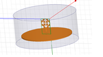
Kindly see the attached picture. I have made a patch antenna.

What I need I want to know how to make it better so that its radiation pattern will become uniform through out the bandwidth almost circular pattern. I want to also make its S11 Better so that its loss is minimum. How to make its gain more better. how to enhance bandwidth.

bandwidth : 2-10 GHz ( If more would be better)
Fractal Antenna.....
no size limitation till yet...

All people kind help is needed.
 

Attachments

  • Untitled.png
    Untitled.png
    33.5 KB · Views: 130

What i need is the only guidance from the experts. So that I can make this antenna better for my research work

- - - Updated - - -

Hello Every one. I have put Some more information. I have attached the Gain plot and S11 parameters. What i want to do is to make S11 more down. Along with I have attached the Radiation pattern (0,90) phi at 1-10 Ghz . At some freq it is not a circular shape. I want it to be identical having more good gain . Kindly suggest some means in order to lower down first the S11 and then Increase Gain . with almost similar radiation pattern at all frequencies.Untitled.png
Untitled2.pngUntitled3.jpg
 

1. try to increase the perimeter of the patch antenna because it is inversly proportional frequency
2. check the dimensions of the radiation box
3. check the waveport dimensions
4. check the convergence
5.try to plot the currenty deinsity graph at low frewuencies and observe that any cancellation occurs
 

hello sir

Can you please tell me following
1. Perimet,er means to increase the whole size of the patch antenna or just copper track area.
2. radiation box i have done about lamda/4
3. waveport i have given on the teflon and min is excited from it
4. can you please tell me about this convergence point more
5. I will plot the current density ....but what i have to do with this..... i have less theoretical knowledge kindly guide
 

Status
Not open for further replies.

Part and Inventory Search

Welcome to EDABoard.com

Sponsor

Back
Top