Continue to Site

Welcome to EDAboard.com

Welcome to our site! EDAboard.com is an international Electronics Discussion Forum focused on EDA software, circuits, schematics, books, theory, papers, asic, pld, 8051, DSP, Network, RF, Analog Design, PCB, Service Manuals... and a whole lot more! To participate you need to register. Registration is free. Click here to register now.

UCC27425 in place of UCC37422/UCC37421 in this circuit...OK?

Status
Not open for further replies.

boylesg

Advanced Member level 4
Joined
Jul 15, 2012
Messages
1,023
Helped
5
Reputation
10
Reaction score
6
Trophy points
1,318
Location
Epping, Victoria, Australia
Activity points
11,697
So a UCC27425 driving an RC combination of 900uH in series with 100nF, I calculate the impedance to be about 560R which give a power dissipation of about 248mW at 12V.
Add the max power dissipation for the PDIP is 350mW.

Does this sound about right to you experts - have I done the calculations correctly?
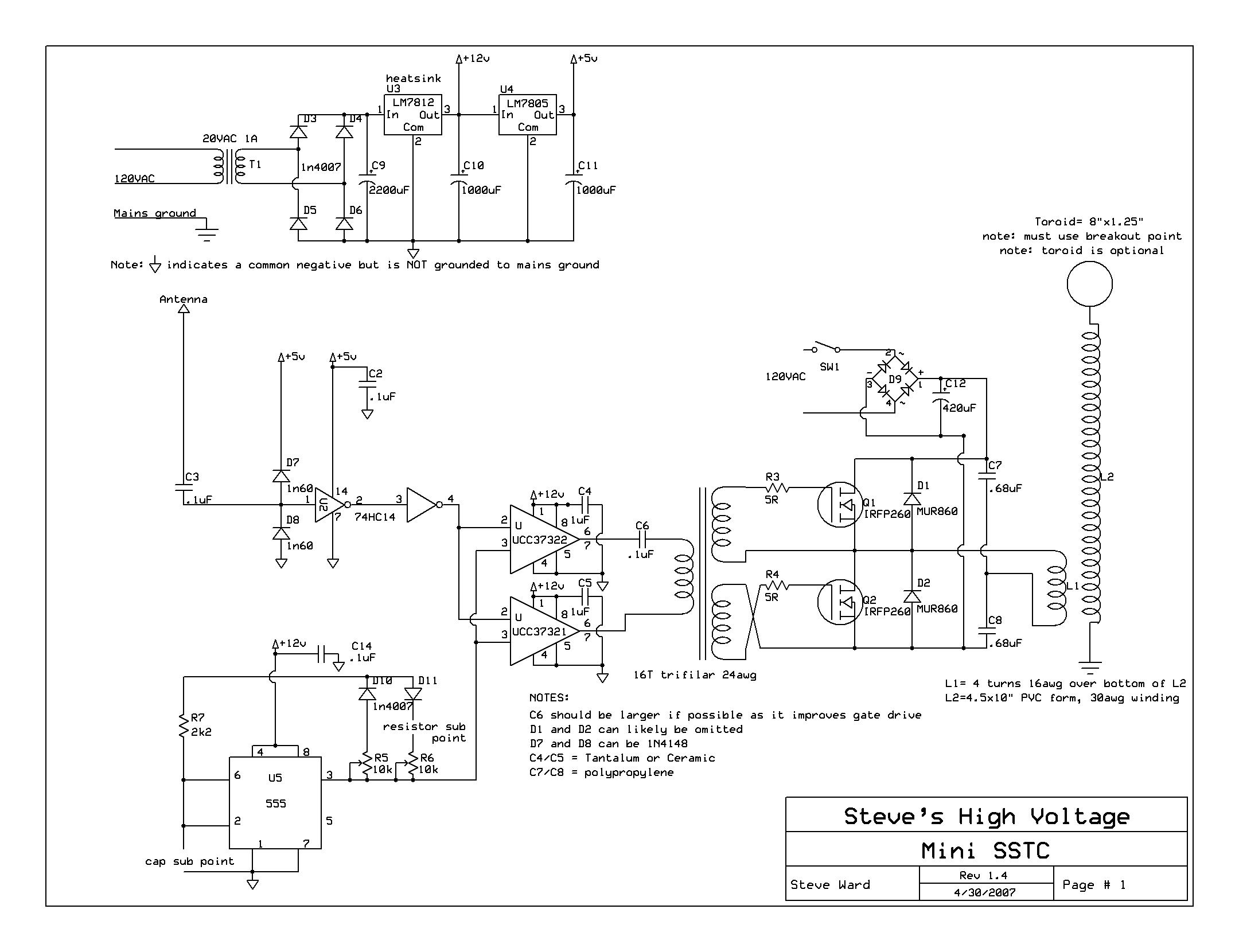
 

Hi,

I just wondered if you've factored ambient temperature into the calculation, for derating purposes, to be sure that the 350mW limit at 25ºC doesn't drop to below 248mW at say 50 or 75ºC.
 

Hi,

I just wondered if you've factored ambient temperature into the calculation, for derating purposes, to be sure that the 350mW limit at 25ºC doesn't drop to below 248mW at say 50 or 75ºC.

No I didn't. I am very much an amateur at electronics so if there are some pearls of wisdom you are prepared to share with me then I am all ears.

What other changes would you make to the circuit of you were to swap the UCC37422/21 out for UCC27425?

I am wondering if sticking a nice big heat sink on top of the pdips would make a difference?

And/or perhaps reducing C6 (in series with the primary of the gate drive transformer) to 56nF in order to increase impedance and reduce current.
As well as perhaps increase the ratio of the gate drive transformer to 1:1.5 or so, such that the voltage on the power FET gates is closer to their 20V max
 

Hi boylesg,

Browse this link if derate ic pd for temperature is something you'd like to look into more.

The snapshot has the formula, basic calculation is easy, good for rule of thumb, the app note is the pdf, I haven't read it but it looks like it may deal with the kind of circuit you are making, so probably worth a look.

PD calculation for ambient temps.JPG

:) ...maybe you could the post a schematic of the circuit you're talking about?! I am also an amateur, so probably wouldn't be able to offer you useful advice about what you're doing, sorry.

I guess the FETs have a datasheet and some graphs that will show what voltage you want on them for the drive needed, not sure pushing them to the VGSth max rating is wise if I've understood what you meant.
 

Attachments

  • slva462.pdf
    59.7 KB · Views: 46

Could have sworn I did in my original post but here it is:

miniSSTCfnlsch.JPG


- - - Updated - - -

From authors comments here I am not sure I understand why he needs up to 9A flowing through the gate drive transformer primary - he talks of increasing the value of C6 to improve gate transformer performance. As I understand it increasing the value of C6 decreases the impedance at a given frequency and inductance and therefore increases the current.

But FETs are voltage operated devices so why would you need amps flowing through the gate drive transformer secondaries, and into the FET gates, as opposed to milliamps?

I am also using IXTK 62N25 as my FETs but even so surely you don't need amps to charge the gates of these quickly?

I hacked up a heat sink for my ucc27425 pdips. I have a draw full of heat sinks I removed from tv circuit boards. I just got one of the medium size ones, with flat sides, that they use for the smaller power transistors. It was long enough to span both pdips and I have cable tied it down using a couple of magnet wire loops I made in my matrix board.

I have also done the pulse generator part of the circuit differently.

1) I have setup a opamp based x10 audio amplifier.
2) An XR 2209 triangle wave generator.
3) A comparator.

And I am using to feed in PWM'ed audio into my gate drive transformer.

Also an astable 555 to feed in a normal square wave and a switch to chose between the two.
 
Last edited:

Hi,

"...why he needs up to 9A flowing through the gate drive transformer primary..." "But FETs are voltage operated devices so why would you need amps flowing through the gate drive transformer secondaries, and into the FET gates, as opposed to milliamps?"
Read about Gate Drive, gate charge..., fast turn on requires (relatively speaking) quite high current - MOSFETs need a bit more than voltage for this kind of application, they also require a good stiff hit of gate current to turn on fast, it's a whole world to explore, take a look at a MOSFET datsheet and get the graph/diagram of "Typical gate charge vs gate-to-source voltage", you need to know the nC for gate drive current.

David's saga relating to his vaporiser project is currently discussing gate drive, pages 3 onwards, and somewhere earlier, and page 4 has some discussion of calculating gate drive requirements, there's also a WinRAR full of gate drive documents there, page 1 or 2 or something.

Hopefully an engineer here who designs this kind of power circuit regularly can explain the why to you, I wouldn't be able to answer your original and continuing to be unanswered question(s), sorry.

What does a mini SSTC do, please?
 

Status
Not open for further replies.

Part and Inventory Search

Welcome to EDABoard.com

Sponsor

Back
Top