Continue to Site

Welcome to EDAboard.com

Welcome to our site! EDAboard.com is an international Electronics Discussion Forum focused on EDA software, circuits, schematics, books, theory, papers, asic, pld, 8051, DSP, Network, RF, Analog Design, PCB, Service Manuals... and a whole lot more! To participate you need to register. Registration is free. Click here to register now.

Stability of the CSA amplifier

Status
Not open for further replies.

tisheebird

Member level 5
Joined
Feb 23, 2017
Messages
88
Helped
0
Reputation
0
Reaction score
0
Trophy points
6
Activity points
662
Hello Friends,

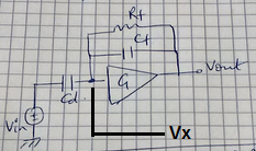
I am designing a Charge sensitive amplifier and would like to study about the stability.
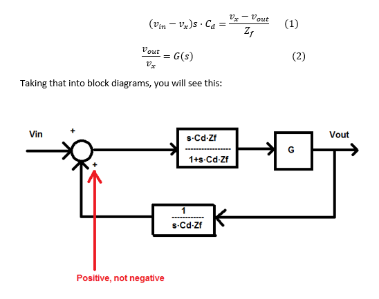
we know, A/1+AB where AB is the open loop gain. If AB is equal to -1 then the system will oscillate. How would I know that AB will be equal -1. Please tell me the how to calculate.

A= G sCdRf/ 1+sRf( Cd+Cf)
B= 1+sRfCf/sRfCd...

Please guide me with the solution.
 

1) Multiply A and B i.e. A(s)*B(s)
2) change s=j·ω
3) Find |A(j·ω)*B(j·ω)|=1
4) Find arg(A(j·ω)*B(j·ω))=+ or - 180º
 
Thank you...But for arg(A(j·ω)*B(j·ω))=+ or - 180º... Should I keep it equal to 180 or 135, because we want min 45deg phase margin.
 

Thank you...But for arg(A(j·ω)*B(j·ω))=+ or - 180º... Should I keep it equal to 180 or 135, because we want min 45deg phase margin.
If you want to design the system in order to have phase maring=45º, then yes. Design in order to have arg(A(j·ω)*B(j·ω))=-135º (yes, MINUS 135º)
 

Thank you... I have tried to do those steps and calculated the value to w(omega) from magnitude and phase expressions.

A= G sCdRf/ 1+sRf( Cd+Cf)
B= 1+sRfCf/sRfCd...
G= gm1r03/ 1+sC2ro3..

I have also tried to convert this into 2nd order standard form to get the value of wn, damping ratio..But can't able to get it.. Please guide me give the solution..
 

Please can anyone make this into 2nd order standard form to get the value of wn, damping ratio..I tried it several times but can't get it.. Please guide me give the solution..
 

tisheebird - you are speaking of a circuit, correct?
Now - when you have some questions, don`t you think it could be helpful to show a diagram of the circuit under question?
I must admit - I do not feel much motivated to guess what you mean with a set of (incorrectly written) formulas like

A= G sCdRf/ 1+sRf( Cd+Cf)
B= 1+sRfCf/sRfCd...
G= gm1r03/ 1+sC2ro3..


Here is a circuit diagram.. i would like to study the stability.. please give me a second order equation..
with wn(omega n) and damping ratio..

https://obrazki.elektroda.pl/2325775600_1488374148.jpg...
 

Put explicit form of your gain formula to a transfer function equation and simplify to a fraction form.
 

"G" in your circuit diagram, seems like a MOSFET amplifier ? If so, the calculation is wrong since you have mixed somehow the OP Amp(has infinite gain at DC) with MOSFET amplifier. Your amplifier has finite gain at DC and is gm1·ro3.
If not, show please what is inside "G" amplifier.

If one has a finite gain amplifier with feedback, the open loop gain "A" is calculated by breaking the loop of the feedback.


Yes G is a folded cascode amplifier. I am really confused how to study the stability of the circuit. I have attached the circuit diagram for which I have to study the stability. Please if you could explain me how to calculate stability for it. Please help me..
Please

https://obrazki.elektroda.pl/5743750700_1488394063.jpg
 

The assumed first order gain characteristic isn't bad as an estimation. There's an additional cascode stage pole, but you can probably ignore it.

The other expressions are however only right if C2 >> Cf, otherwise the amplifier output impedance matters.

As a short cut, it's rather unlikely to drive an amplifier with a single gm stage into instability.


In this case, C2 is nearly same as cf..
 

In my analysis, First I calculated the open loop gain = -gm1ro3/ 1+sC2ro3.

Secondly, I put the feedback network values by calculating the falling time.. Now I have to calculate the stability for this circuit.
I know the conditions and basics about bode plot, but I am struggling in doing manual calculations. Please show me once how to calculate the open loop gain "A" and feedback network (B) for this circuit.


https://obrazki.elektroda.pl/5743750700_1488394063.jpg
 

Your circuit is a shunt shunt topology. In order to calculate open loop gain "A" , you have to actually break the feedback loop and calculate it like it is shown in the book of Sedra-Microelectronic circuits.

In this case, as you have calculated the transfer function of the cascode amplifier and it has infinite input impedance, then you can write equations like in an op amp and solve them. See attached picture.


- - - Updated - - -

Vx in the attached picture is show here:
 

Attachments

  • Microelectronic circuits-page 886.pdf
    179.2 KB · Views: 107
Your circuit is a shunt shunt topology. In order to calculate open loop gain "A" , you have to actually break the feedback loop and calculate it like it is shown in the book of Sedra-Microelectronic circuits.

In this case, as you have calculated the transfer function of the cascode amplifier and it has infinite input impedance, then you can write equations like in an op amp and solve them. See attached picture.


- - - Updated - - -

Vx in the attached picture is show here:


Thanks a lot... I have attached this picture, please let me know if I am doing it correct. If yes, what value should I take for G(s) in this equation.
Should I take G(s) = -gm1ro3/1+ sC2ro3 or just -gm1ro3...

https://obrazki.elektroda.pl/1370454800_1488403004.jpg
 

In this case, as you have calculated the transfer function of the cascode amplifier and it has infinite input impedance, then you can write equations like in an op amp and solve them.
Unfortunately the amplifier is rather an OTA than an OP and the calculated G is only correct for Co >> Cf, as mentioned. The exact transfer function is even more complex than the complete loop gain.

According to SapWin4

G = -gm*Ro*(1+(Cd+Cf)Rf s)/(1+(CdRo+CdRf+CfRf+CoRo)s + (CfCd+CoCd+CoCf)RfRo s²)

Gcirc.jpg

loop gain = -gm*Ro*(1+(CfRf s)/(1+(CdRo+CdRf+CfRf+CoRo)s + (CfCd+CoCd+CoCf)RfRo s²)
 
Unfortunately the amplifier is rather an OTA than an OP and the calculated G is only correct for Co >> Cf, as mentioned. The exact transfer function is even more complex than the complete loop gain.

According to SapWin4

G = -gm*Ro*(1+(Cd+Cf)Rf s)/(1+(CdRo+CdRf+CfRf+CoRo)s + (CfCd+CoCd+CoCf)RfRo s²)

View attachment 136609

loop gain = -gm*Ro*(1+(CfRf s)/(1+(CdRo+CdRf+CfRf+CoRo)s + (CfCd+CoCd+CoCf)RfRo s²)


Thank you.. But if I remember properly, my Co is roughly same as Cf...So how to proceed..??
 

Unfortunately the amplifier is rather an OTA than an OP and the calculated G is only correct for Co >> Cf, as mentioned. The exact transfer function is even more complex than the complete loop gain.

According to SapWin4

G = -gm*Ro*(1+(Cd+Cf)Rf s)/(1+(CdRo+CdRf+CfRf+CoRo)s + (CfCd+CoCd+CoCf)RfRo s²)

View attachment 136609

loop gain = -gm*Ro*(1+(CfRf s)/(1+(CdRo+CdRf+CfRf+CoRo)s + (CfCd+CoCd+CoCf)RfRo s²)


Thank you, But my Co is roughly same as Cf... How to proceed further...
 

Yes I know. You need to refer to the exact G expression considering all circuit elements, as calculated above.

That's what SapWin calculates for the CSA transfer function (closed loop gain). Please rewrite respectively.
Code:
v1:

+ (  - Hgm Cd Rf Ro + Cd Ro ) j w
- (  Cf Cd Rf Ro ) w^2
------------------------------------------------------------------------------
+ (  Hgm Ro +1 )
+ (  Cd Ro + Cd Rf + Hgm Cf Rf Ro + Cf Rf + Co Ro ) j w
- (  Cf Cd Rf Ro + Co Cd Rf Ro + Co Cf Rf Ro ) w^2

csa_cl.jpg
 
Status
Not open for further replies.

Similar threads

Part and Inventory Search

Welcome to EDABoard.com

Sponsor

Back
Top