ismu
Full Member level 2
I build servo controller with two type of topology , i have few questions
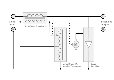
1. -series transformer in first topology (auto trfmr is at output)is taking more current than 2nd(auto trfmr is at input) with same load and voltage. But which is giving rated output regulated voltage 230v from lower input voltage 90v than 2nd topology (which is 120v) , which topology is good.?
1st topology :

[above found at: microsystemservices .files .wordpress .com /2011 /05 /servo -design-v2-small .png]
2nd topology :

[above found at: electricalinfo .in /media /tech /fig-ss /figssServo .gif]
2. -seriers transformer i kept as step down configuration , do I need to swap boost config? Or what ratio i have to keep?
3. - when input is 150v then servo out is 230v , if input is suddenly come to normal 230v and currently servo is in boost mode, so 210v input will be boosted to 310v high volt, so system will reduce to back 230v by rotating autotransformer . But 2-3secs will take to normalize & there will be high volt 310v on the load in these time. How can I solve this issue.
1. -series transformer in first topology (auto trfmr is at output)is taking more current than 2nd(auto trfmr is at input) with same load and voltage. But which is giving rated output regulated voltage 230v from lower input voltage 90v than 2nd topology (which is 120v) , which topology is good.?
1st topology :
[above found at: microsystemservices .files .wordpress .com /2011 /05 /servo -design-v2-small .png]
2nd topology :
[above found at: electricalinfo .in /media /tech /fig-ss /figssServo .gif]
2. -seriers transformer i kept as step down configuration , do I need to swap boost config? Or what ratio i have to keep?
3. - when input is 150v then servo out is 230v , if input is suddenly come to normal 230v and currently servo is in boost mode, so 210v input will be boosted to 310v high volt, so system will reduce to back 230v by rotating autotransformer . But 2-3secs will take to normalize & there will be high volt 310v on the load in these time. How can I solve this issue.
Last edited by a moderator: