Continue to Site

Welcome to EDAboard.com

Welcome to our site! EDAboard.com is an international Electronics Discussion Forum focused on EDA software, circuits, schematics, books, theory, papers, asic, pld, 8051, DSP, Network, RF, Analog Design, PCB, Service Manuals... and a whole lot more! To participate you need to register. Registration is free. Click here to register now.

[Moved]: OP-AMP current mirror AC analysis

Status
Not open for further replies.

ENMA

Newbie level 4
Joined
Apr 28, 2014
Messages
6
Helped
0
Reputation
0
Reaction score
0
Trophy points
1
Activity points
43
Hi guys,

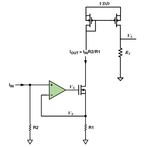
I am having a trouble to understand where and how is best place to measure ACL of the attached schematic.
sensor diagram.png

Since Vs is the real output, I can't figure where is the best node to insert AC source to obtain vout(f)/vin(f)and the bandwidth of circuit. There is no real feedback between Vs and VY node, and I am little bit confused regarding the loop gain and ACL of the circuit.

In general I am using this circuit as a current sensor (sensing Iin).

Thank you.
 

Re: OP-AMP current mirror AC analysis

(1) Iin=Idc+Iac, Vout/Iac
(2) Iin=Idc, Insert Vac in series with R2, Vout/Vac

What do you mean by "ACL" ?
 
  • Like
Reactions: ENMA

    ENMA

    Points: 2
    Helpful Answer Positive Rating
Re: OP-AMP current mirror AC analysis

There is a indirect feedback between Vs and VY node because upper two MOS act asa current mirror and therefore Vs is strongly related to Iout that is also related to Iin via OPAMP+Resistors.This circuit acts as "Current Input-Voltage Output" principal so it's a simply Transimpedance amplifier/converter.If you intend to make an AC analysis, you should observe Vout/Iin quantity.
 
  • Like
Reactions: ENMA

    ENMA

    Points: 2
    Helpful Answer Positive Rating
Re: OP-AMP current mirror AC analysis

(1) Iin=Idc+Iac, Vout/Iac
(2) Iin=Idc, Insert Vac in series with R2, Vout/Vac

What do you mean by "ACL" ?

Thank you.
But this way the gain has Ohm units, quite confusing in terms of gain which is usually a unit-less constant.

* ACL = as Erikl mentioned, A means gain CL means Closed Loop.

There is a indirect feedback between Vs and VY node because upper two MOS act asa current mirror and therefore Vs is strongly related to Iout that is also related to Iin via OPAMP+Resistors.This circuit acts as "Current Input-Voltage Output" principal so it's a simply Transimpedance amplifier/converter.If you intend to make an AC analysis, you should observe Vout/Iin quantity.

Thank you for the reply, BigBoss.
As I answered to Pancho, what is the meaning of the gain when it represented with Ohms?
So what you are suggesting is also applicable for the bandwidth analysis of the circuit?

Regarding the VS~VY connection, yes you are right but there is no feedback from VS to VY. A change in VY will change VS, but I don't see how is it working in the opposite direction?
Maybe I am missing something with the basic definitions, closed-loop gain defined as the gain resulted from a feedback network isn't it?

Eli.
 

I think the OP means "A" (as in general Gain, irrespective of whether it is Av or Ai) and "CL" for "Closed Loop".
 

Re: OP-AMP current mirror AC analysis

Thank you for the reply, BigBoss.
As I answered to Pancho, what is the meaning of the gain when it represented with Ohms?
So what you are suggesting is also applicable for the bandwidth analysis of the circuit?

Regarding the VS~VY connection, yes you are right but there is no feedback from VS to VY. A change in VY will change VS, but I don't see how is it working in the opposite direction?
Maybe I am missing something with the basic definitions, closed-loop gain defined as the gain resulted from a feedback network isn't it?

Eli.

If somehow VS is increased, consequently ( mirroring of the current so the current have to have same amount ) Iout will be increased then this will increase VY after that this feedback will decrease VGS voltage of the MOS so the Iout will be "regulated" in this consequence.This is very well known technique in Voltage/Current Regulators and you can find lot of docs. about it in IC manufacturers' websites.
The Bandwidth is simply found by doing a Closed Loop AC simulation even in LTSpice simulator.But the models of the components should be well defined in terms of small signal mode.Output node will obviously VS, Input node will absolutely Iin so you will find a Impedance Transfer Function and surely some "poles and zeros". This is the Frequency Response.
 
  • Like
Reactions: ENMA

    ENMA

    Points: 2
    Helpful Answer Positive Rating
Status
Not open for further replies.

Similar threads

Part and Inventory Search

Welcome to EDABoard.com

Sponsor

Back
Top