Continue to Site

Welcome to EDAboard.com

Welcome to our site! EDAboard.com is an international Electronics Discussion Forum focused on EDA software, circuits, schematics, books, theory, papers, asic, pld, 8051, DSP, Network, RF, Analog Design, PCB, Service Manuals... and a whole lot more! To participate you need to register. Registration is free. Click here to register now.

Self Driven Piezo not yielding output

Status
Not open for further replies.

electronika.design

Junior Member level 1
Joined
Feb 25, 2016
Messages
19
Helped
0
Reputation
0
Reaction score
0
Trophy points
1
Activity points
151
Hi all,

I am trying to work out a self driven 3 wire piezo...
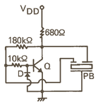
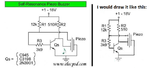
The circuit is very easy and I have attached it below...
The resistor values are 10k and 180k with an inductance of 60mH, while the circuit should work fine at +5V supply and the frequency for piezo is 3KHz.

Even though having all the information correct(I have seen this circuit work in same condition with same values of everything), My circuit seems to have lost its way somewhere and I am not able to troubleshoot it.

Please can someone point out where I could be going wrong???
I am not sure if my inductor is doing good, how to I test its condition??
Also if i remove the inductor and connect GND instead to emitter, the buzzer beeps but at very low output...
Thanks...

Piezo.PNG
 

The collector of your transistor is doing nothing. Piezo beepers do not have an inductor. Here are two of them:
 

Attachments

  • piezo beeper.PNG
    piezo beeper.PNG
    5.8 KB · Views: 61
  • piezo beeper2.png
    piezo beeper2.png
    81.2 KB · Views: 57

The datasheet doesn't specify 60 mH for this circuit. How do you know that the value is right?

How did you connect the disc? I presume the feedback tab goes to the base terminal.

Also if i remove the inductor and connect GND instead to emitter, the buzzer beeps but at very low output...
You should try the regular common emitter circuit from the datasheet instead.
 

The datasheet doesn't specify 60 mH for this circuit. How do you know that the value is right?

How did you connect the disc? I presume the feedback tab goes to the base terminal.

You should try the regular common emitter circuit from the datasheet instead.


I asked for a working sample for the seller of piezo... And this is the circuit I was forwarded with a video clip of it working... I asked for the values also, hence I know the values for sure.

And yes the feedback goes to the base but through a resistor... Actually I want to squeeze out more output that is why I am using an trying to use with inductor...
Thanks..
 

The datasheet you found shows one schematic like the one you posted and two schematics like the ones I posted. Somebody does not know anything about a simple piezo beeper, the seller of your circuit or the circuits I found. Maybe your seller got the emitter and collector pins of the transistor reversed?
Why not buy a beeper that works properly from a local distributor (not ebay) and look inside it?
 

I asked for a working sample for the seller of piezo... And this is the circuit I was forwarded with a video clip of it working... I asked for the values also, hence I know the values for sure.
I believe that the oscillator topology can work under circumstances, but it may depend on additional parameters of the inductor like parallel capacitance, series resistance respectively loss factor, saturation current. Using the same "values" doesn't involve an identical inductor I presume.
 

You did not show a photo or the datasheet of the piezo beeper you have. The ones that are very loud are mounted in a resonant plastic case and the case is designed for the resonant frequency of the piezo.
I have one and it is powered from only 3V and it is loud. With a 9V battery it can be heard far away.
 

Status
Not open for further replies.

Similar threads

Part and Inventory Search

Welcome to EDABoard.com

Sponsor

Back
Top