Continue to Site

Welcome to EDAboard.com

Welcome to our site! EDAboard.com is an international Electronics Discussion Forum focused on EDA software, circuits, schematics, books, theory, papers, asic, pld, 8051, DSP, Network, RF, Analog Design, PCB, Service Manuals... and a whole lot more! To participate you need to register. Registration is free. Click here to register now.

optocoupler voltage drop

Status
Not open for further replies.

mamech

Full Member level 3
Joined
Nov 9, 2010
Messages
176
Helped
0
Reputation
0
Reaction score
0
Trophy points
1,296
Activity points
3,135
hello

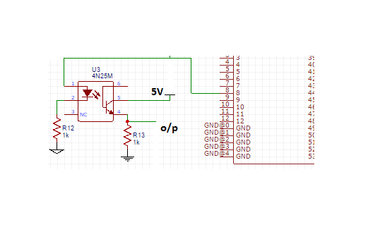
I am trying to make isolation from low voltage side to high voltage side. the low voltage side sends pwm signal that has 1-5 volts range, the problem is that the optocoupler 4N35 that I am using have already around 0.4 volts, and I need to maintain the same range 1-5 volts on the other side.

is there workaround to make the output to be linear in 1-5 volts range ?
 

Hi,

show your circuit... or at list a draft of what you want to achieve.

Are you talking about analog signals or digital signals?

Klaus
 

sorry for late reply, I just did not develop this part in the circuit for a while, and now I am into it again.

the circuit is shown below:


my problem is, when the pwm output from microcontroller is around 5 volts (full pwm output), the output on the other side of the optocoupler is less than 5 (it was about 4.7 or so) because of drop of the optocoupler itself.

I want to reduce or eliminate this effect, so I get a linear scaling (5 volts on optocoupler output when I give 5 volts on pwm side, and 0 volts on optocoupler output when I give 0 volts on pwm side)

are there any suggestions how can I achieve this?
 

Hi,

Read about CTR of 4N35.
The output is simply not in saturation.

--> either use more drive curent. Or less load corrent.

Klaus
 
  • Like
Reactions: mamech

    mamech

    Points: 2
    Helpful Answer Positive Rating
Hi,

Read about CTR of 4N35.
The output is simply not in saturation.

--> either use more drive curent. Or less load corrent.

Klaus

I have looked in datasheet and looked at CTR curves, but I have some questions so I become sure that I got it:
1-you told me use more drive current, so this means to use resistor less than 1k that is used in pwm side of optocoupler , right?
2- you told me to use less load current, this means to use resistor less than 1k that I used with optocoupler emitter?
 

sorry for late reply, I just did not develop this part in the circuit for a while, and now I am into it again.

the circuit is shown below:


my problem is, when the pwm output from microcontroller is around 5 volts (full pwm output), the output on the other side of the optocoupler is less than 5 (it was about 4.7 or so) because of drop of the optocoupler itself.

I want to reduce or eliminate this effect, so I get a linear scaling (5 volts on optocoupler output when I give 5 volts on pwm side, and 0 volts on optocoupler output when I give 0 volts on pwm side)

are there any suggestions how can I achieve this?

Have the optocoupler drive a low RDSon Mosfet. But if your PWM is fast, the output may not be a proper square wave. Plus, it will be inverted.
The best solution would be to use a CD4050 CMOS non-inverting buffer after the optocoupler.
 

    V

    Points: 2
    Helpful Answer Positive Rating
Status
Not open for further replies.

Similar threads

Part and Inventory Search

Welcome to EDABoard.com

Sponsor

Back
Top