Continue to Site

Welcome to EDAboard.com

Welcome to our site! EDAboard.com is an international Electronics Discussion Forum focused on EDA software, circuits, schematics, books, theory, papers, asic, pld, 8051, DSP, Network, RF, Analog Design, PCB, Service Manuals... and a whole lot more! To participate you need to register. Registration is free. Click here to register now.

RC extraction in SoC encounter

Status
Not open for further replies.

oAwad

Full Member level 2
Joined
Feb 15, 2017
Messages
136
Helped
0
Reputation
0
Reaction score
0
Trophy points
16
Activity points
1,312
I'm trying to understand the meaning of "relative C threshold" and "total C threshold" when I select timing->Analysis condition->specify RC Extraction mode.
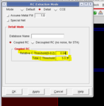
ask1.PNG

Does it depend on PDK and if yes, where can I find this info in my PDK ?

Another question, is it possible to generate only the coupling capacitance in the layout ? (nothing in SPEF file except coupling cap.)

Thanks
 

when you set process node using setDesignMode -process , the tool will automatically set the recommended value. you can refer to encounter user guide for the exact meaning。Not sure if you can generate only the coupling capacitance,never tried this before。
 

when you set process node using setDesignMode -process , the tool will automatically set the recommended value. you can refer to encounter user guide for the exact meaning。Not sure if you can generate only the coupling capacitance,never tried this before。

I used Nangate Open Cell Library 45nm for my design. When I entered "getDesignMode" I found design mode was set to process 90.

So I have some questions here:

1) So should I have set the design mode to 45nm process before routing ? or it's fine if I specify it just before RC extraction ?
2) How it wasn't automatically set by encounter when I first imported my LEF and netlist files ?
3) When I specified the design mode to 45nm, I got the same coupling capacitance values between the wires (given same conditions)...should the values be different between 45nm extraction and 90nm extraction ? or since given the same conditions (same width, separating distance, common length,...) there will be no change ?


Sorry for my many questions :)

1) set it to 45 at the time you start encounter. it affects all sorts of implementation tasks.
2) user has to set, not the tool. tool cannot infer technology node from LEF.
3) depends on what type of extraction you performed. are you using captables or QRC files?
 

1) set it to 45 at the time you start encounter. it affects all sorts of implementation tasks.
2) user has to set, not the tool. tool cannot infer technology node from LEF.
3) depends on what type of extraction you performed. are you using captables or QRC files?

I'm using captables provided by Nangate corporation so should I apply a scaling factor or as long as the company provides it then I won't have to scale ?

Is there any commands other than "setDesignMode" I have to perform in the P&R process ? (what I do is import LEF & timing -> floorplan -> power rings -> place std cells -> nanoroute -> optimization -> RC extraction -> timing reports -> export GDSII)...anything I'm missing ?
 

Status
Not open for further replies.

Part and Inventory Search

Welcome to EDABoard.com

Sponsor

Back
Top