Continue to Site

Welcome to EDAboard.com

Welcome to our site! EDAboard.com is an international Electronics Discussion Forum focused on EDA software, circuits, schematics, books, theory, papers, asic, pld, 8051, DSP, Network, RF, Analog Design, PCB, Service Manuals... and a whole lot more! To participate you need to register. Registration is free. Click here to register now.

New to breadboard, unable to recognize components

Status
Not open for further replies.

davedave123

Newbie level 3
Joined
Feb 22, 2017
Messages
4
Helped
0
Reputation
0
Reaction score
0
Trophy points
1
Activity points
37
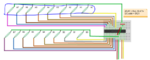
Hi, I am new to using the breadboard, and in the huge project I am working on I am trying to connect 4 multiplexors to a raspberry pi. However, in the tutorial I cannot recognize the parts highlighted. Can anyone tell me what these are? maybe capacitors?

Also, how do I connect 8 of these things in parallel as shown in the image?

reference: **broken link removed**
 

Attachments

  • breadboard.PNG
    breadboard.PNG
    212.9 KB · Views: 72

Hi,

the text in your links says it.
and the headline of the referenced internet site: These are reed-switches.

Klaus
 

Edit: So these are reed switches (obvious mistake)
how are the wires connected, shows a single green wire connecting to 8 reed switches.
 

Hi,

how are the wires connected, shows a single green wire connecting to 8 reed switches.
this is correct.

It is like in your house. One wire coming from the grid goes to several switches in your house. Form the switches there are independet lines to the load(s).

Klaus

Btw: instead of connecting 8 MUXes to the 64 switches...
* I´d rather use a keyboard IC
* or bulid my own 8 x 8 matrix.
 

Hi,


this is correct.

It is like in your house. One wire coming from the grid goes to several switches in your house. Form the switches there are independet lines to the load(s).

Klaus

Btw: instead of connecting 8 MUXes to the 64 switches...
* I´d rather use a keyboard IC
* or bulid my own 8 x 8 matrix.

thanks,

I decided to follow the instructions here, with the python code already there for me.

regarding connecting the wires from one to 8 switches, I don't get how they connect since a wire would have only one end, is there a way to have the wires connect to multiple ends?
 

Hi,

since a wire would have only one end,
No, a wire has two ends.
In your case one end goes to the switch, the other end to the MUX input.
The pictures shows which wire to which MUX_pin goes.

I recommend to read MCP23017 datasheet and compare it with the breadboard picture.

Klaus
 

Hi,


No, a wire has two ends.
In your case one end goes to the switch, the other end to the MUX input.
The pictures shows which wire to which MUX_pin goes.

I recommend to read MCP23017 datasheet and compare it with the breadboard picture.

Klaus

what i mean is, say for one reed switch, i connect one end with the wire that connects through a certain hole in the breadboard. the other side however has wires connecting to the same green wire.
How do i connect the 8 reed switches to the same green wire?
 

You could just connect the green wire to a hole and connect the reed switches each to another hole that has continuity with the hole to which you connected the green wire. The number of holes that have continuity with the hole with green wire may not be enough so you jumper two sets of continuous rows or columns so you can have enough continuous holes for your connections.

Hope that is what you asked for.
 

Edit: So these are reed switches (obvious mistake)
how are the wires connected, shows a single green wire connecting to 8 reed switches.

Most of the breadboards have a single line going all the way to the end of the board(mostly at the edge of the long dimension and have holes of group of 5 along the line). So you put your MCP23017 or whatever you want to mmiddle of the board(each set of legs are on each side of the middle ridge).
 

Status
Not open for further replies.

Similar threads

Part and Inventory Search

Welcome to EDABoard.com

Sponsor

Back
Top